background image

                             Confidential                                                                Page 8 of 8 


See3CAM_80   


         Hardware User Manual 


14-Aug-2013 


Figure 7: Connecting USB3.0 Cable to Superspeed Port 


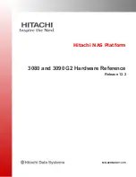
After the insertion of USB3.0 Cable with USB3.0 connector on the board and USB Host, the LED 
(D7) will glow in Red colour. This indicates that the board is powered ON.  


Figure 8: Status LED indicating Board Powered ON.  

7  Conclusion 

This document describes How to connect See3CAM_80 board to USB3.0 Host and how to get it 
working. For further information please refer datasheet and application note for reference 
schematic on trigger and Strobe usage.


Summary of Contents for See3CAM 80

Page 1: ...ge 1 of 8 See3CAM_80 Hardware User Manual 14 Aug 2013 e con Systems India Pvt Ltd 17 54 th Street Ashok Nagar Chennai 600083 www e consystems com See3CAM_80 Hardware User Manual Revision 1 0 Wednesday...

Page 2: ...ction 4 3 Scope 4 4 Disclaimer 4 5 Description 4 6 Setting up the See3CAM_80 5 6 1 See3CAM_80 to PC Host interconnecting Cable 5 6 2 Connecting the board with Host 6 6 2 1 Identification of USB3 0 Con...

Page 3: ...Confidential Page 3 of 8 See3CAM_80 Hardware User Manual 14 Aug 2013 See3CAM_80 1 Revision History Rev Date Description Author 1 0 August 14 2013 Initial Draft Kasthuri Rangan...

Page 4: ...ny 3 Scope The scope of this document is limited to providing necessary overview of the See3CAM_80 camera board and how to use the same on a typical PC based environment 4 Disclaimer The specification...

Page 5: ...3 0 Superspeed client device The See3CAM_80 camera is supplied along with a USB cable to connect to the USB Type A host port The following sections describe the parts supplied in the kit See3CAM_80 bo...

Page 6: ...e board is connected to USB2 0 Highspeed port only VGA resolution at 30 fps will be streamed e CAMView will show white screen when any other resolution is selected 6 2 1 Identification of USB3 0 Conne...

Page 7: ...able inserted in USB3 0 connector 6 2 3 Connecting the board to Host Identify a USB3 0 port The port which has the below logo is USB3 0 Port Figure 5 Superspeed USB 3 0 Logo The USB3 0 cable needs to...

Page 8: ...the board and USB Host the LED D7 will glow in Red colour This indicates that the board is powered ON Figure 8 Status LED indicating Board Powered ON 7 Conclusion This document describes How to conne...

Reviews: