Instruction Manual: D-Box + QUASAR T25 A3 + ASG UD
Date: 18-12-17 Revision: 02 Cod: DYN62-3.02
3
D-Box’s input signals are typical of the installation controller. As a result, response times of the controller
components are inherent to it even though the total response times of the D-Box + QUASAR T25 A3 + ASG
UD unit are considered as standard.
In the case of checking the installation or carrying out a manual rescue, it must be checked that the D-Box
is set at the correct operation mode for each of these situations so as to prevent unwanted jamming in the
safety wears.
The parking or anti-creep system incorporated in the QUASAR T25 A3 governor to detect uncontrolled
movements, must always include a 24V coil in order to operate correctly along with the D-Box.
3 DESCRIPTION OF THE UNIT
3.1 COMPONENTS OF THE SYSTEM
The components making up the system are:
CONTROL SYSTEM
The D-Box operates as a control system.
GOVERNOR– SAFETY GEAR – DRIVING BAR
The QUASAR T25 A3 model two-way governor, operates as a UCM actuator.
Finally, the two-way safety gear, ASG UD model by Dynatech incorporated in the QUASAR T25 A3, will operate as
a braking device.
3.2 OPERATION AS A UNIT
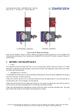
As can be seen in figure 2, the D-Box electronic device is connected to the installation controller and the QUASAR
T25 A3 governor’s parking system. D-Box connection is described in the D-Box's manual for use and maintenance.
The governor in the Quasar-T25 assembly is of the “on-board” type. This means that the governor moves along with
the car. The assembly is anchored to the frame's upright by four screws. The return part will be anchored to the
upright at the height determined by the installer.
Note: This manual displays partial information on the instructions for use and maintenance of this product. Please refer to the customer
area in Dynatech’s website in order to consult the full manual; http://customers.dynatech-elevation.com/
Summary of Contents for D-BOX
Page 2: ......


