


24
3. The opening screen, shown in
Figure 12
, is called the Data
Screen. It contains a large data trend chart that can be
adjusted for both the X(time) and Y(flow rate) axis. This
screen also contains real-time information regarding flow
rate, totalizer accumulations, system signal strength and
diagnostic data. The indicator in the lower right-hand
corner will indicate communications status. If a red
ERROR
is indicated, click on the Communications button
on the top bar. Click on Initialize. Choose the appropriate
COM port and RS232. Proper communications are
established when a green
OK
is indicated in the lower right-
hand corner of the PC display.
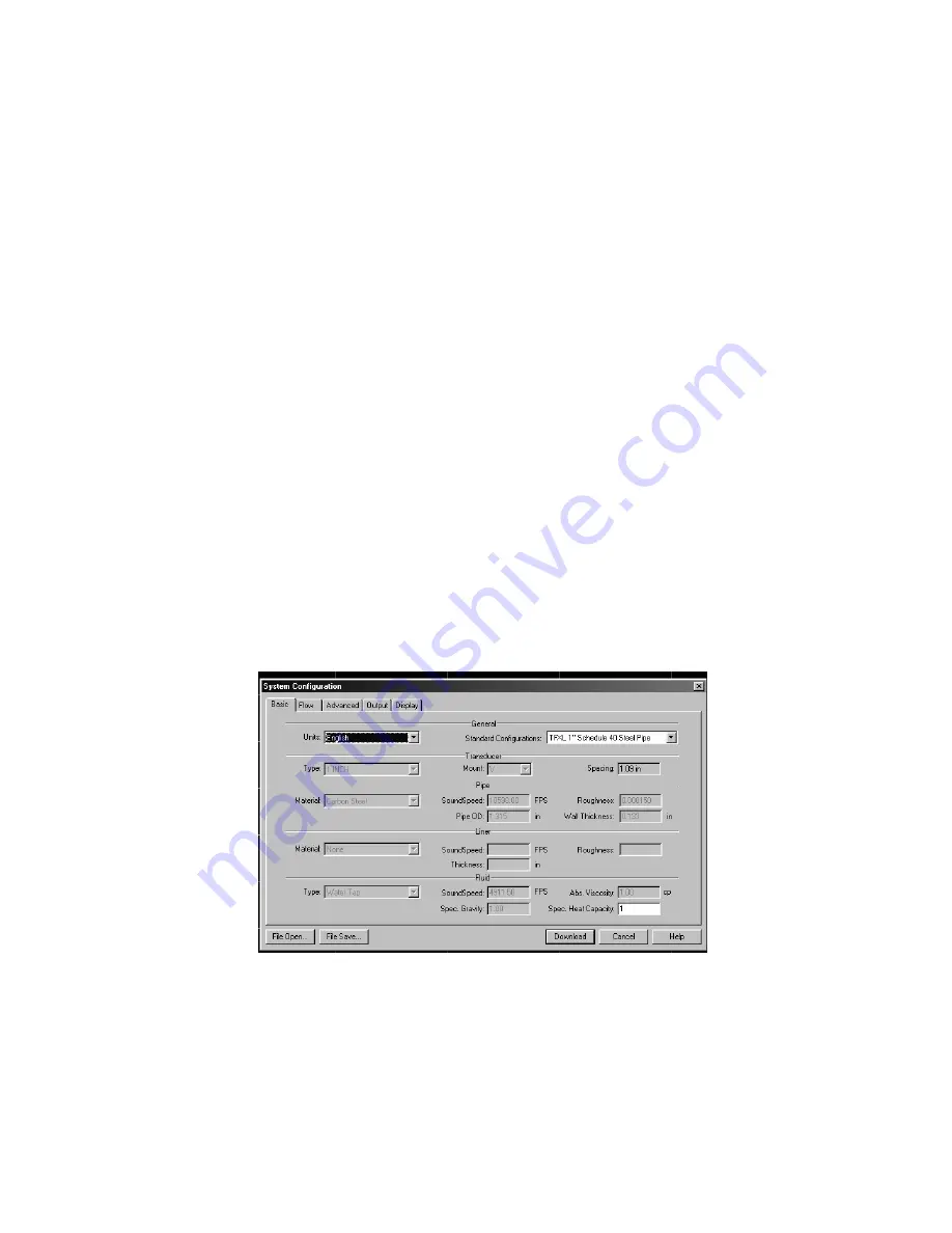
4. Click on the button labeled
Configuration
for updating flow
range, liquid, pipe and I/O operating information. The first
screen that appears after clicking the
Configuration
button
is the
BASIC
tab. See
Figure 13
.
5.
BASIC
TAB—See
Figure 13
•
General Units
allows selection of either English (U.S.) or
Metric units of measure. If measurements of the pipe are to
be entered in inches, select English. If pipe measurements
Figure 13
Basic Tab
Summary of Contents for TFXL
Page 1: ...1 MODEL TFXL ULTRASONIC FLOW METER Installation and Operating Instructions...
Page 2: ...2...
Page 9: ...9 SOUND GUIDES CLAMP PC INTERFACE CABLE...
Page 41: ...41...
Page 42: ...42 NOTES...
Page 43: ...43...


