background image


DS752LT5  User  Manual   23 
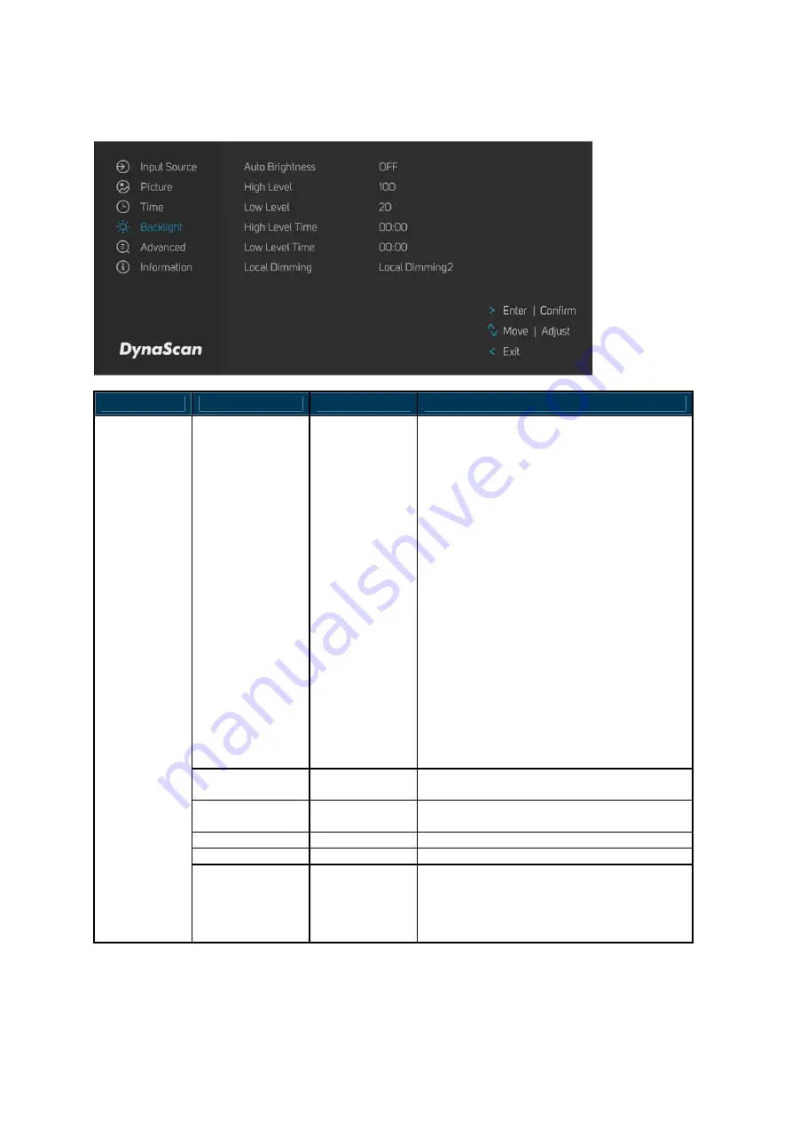
4. Backlight 


ITEM 1 

ITEM 2 

DEFAULT


DESCRIPTION


Auto Brightness 

Off 

A.    If the AUTO BRIGHTNESS is “Off”, the 

screen brightness will remain at HIGH 
LEVEL brightness value. 

B.    If the AUTO BRIGHTNESS is “Auto”, 

the brightness of display will be 
adjusted according to the ambient light. 
When ambient light is bright, the screen 
will adjust to the High Level brightness 
value set; when ambient light is dark, 
the screen will adjust to the Low Level 
brightness value set. 

C.    When the Timer (“High Level Time” & 

“Low Level Time”) mode is set, the 
display will automatically switch the 
brightness according to the time set. 

D.    When setting “Mix” mode, Timer and 

Light sensor will work at this mode.   
For example, setting "High Level Time 
= 8:00am" and "Low Level Time = 
6:00pm", the light sensor will detect 
environment brightness and then 
display will adjust the value of High 
Level during 8:00am and 6:00pm. 

High Level 

100 

Adjusts the highest brightness level.   
Range 0 – 100. 

Low Level 

20 

Adjusts the lowest brightness level.   
Range 0 – 100. 

High Level Time 

00:00 

Set high level time. 

Low Level Time 

00:00 

Set low level time. 

Backlight 

Local Dimming 

Local  Dimming 

Adjusts the contrast.    UDR1~3 is the 
highest contrast.    Local Dimming 1 is the 
lowest contrast. 
(Local Dimming 1, Local Dimming 2, UDR1, 
UDR2 and UDR3) 


Summary of Contents for DS752LT5

Page 1: ...USER MANUAL DS752LT5 75 Clean Back Digital Signage 64606 V2 02...

Page 2: ...ng Remote Control Batteries 8 Bien d buter 9 Contenu 9 Mise en place et remplacement des piles de la t l commande 9 Installation 11 Mounting 11 Wall Mounting 14 Connecting to a Power Source 14 Connect...

Page 3: ...can is firmly committed to its environmental protection efforts and we believe that reducing our products impact on the environment is of the utmost importance We are dedicated to meet the latest envi...

Page 4: ...interference at his own expense CAUTION Any changes or modifications not expressly approved by the grantee of this device could void the user s authority to operate the equipment RF exposure warning...

Page 5: ...ATTENTION Tout changement ou modification non express ment approuv par le responsable de la conformit peut r voquer l autorit de l utilisateur employer l appareil en question Avertissement relatif au...

Page 6: ...hile cleaning Do not use extreme force or any sharp or pointed objects to touch the display Do not drop or allow any object to fall to the display Do not operate the display with wet hands to avoid el...

Page 7: ...toyage N exercez pas une force excessive et n utilisez pas d objets tranchants ou pointus pour toucher l cran Ne laissez pas tomber l cran et ne laissez aucun objet tomber dessus Afin d viter tout cho...

Page 8: ...nd other particles Unplug the LCD immediately and contact a DynaScan certified service professional as soon as possible when any of the following situations occurs Damaged power cord or power plug If...

Page 9: ...pour tout transport ult rieur Nettoyez l arri re de l cran LCD au moins une fois par mois afin d liminer la poussi re et autres particules D branchez imm diatement l cran LCD et contactez un r parate...

Page 10: ...S A Canada EU Except U K Japan Taiwan Voltage 120V 230V 100V 110V NEMA TYPE NEMA 5 15 CEE 7 7 NEMA 1 15 NEMA 5 15 IEC Display Plug IEC Plug TYPE IEC320 C13 Installing and Replacing Remote Control Batt...

Page 11: ...de fiche Am rique du Nord Europe continentale Japon Ta wan Forme de la fiche R gion tats Unis Canada UE Hors R U Japon Ta wan Tension 120V 230V 100V 110V TYPE NEMA NEMA 5 15 CEE 7 7 NEMA 1 15 NEMA 5...

Page 12: ...DS752LT5 User Manual 10 Remarque Si la t l commande ne doit pas tre utilis e pendant une p riode prolong e nous vous recommandons d en retirer les piles...

Page 13: ...disasters DynaScan recommends having certified professionals to evaluate the installation site and perform the mounting operation Do not to cover the vent and or the heat sink in order to ensure prope...

Page 14: ...rotated clockwise when looking at the front of the display such that the left edge becomes the top edge Front Portrait mode Rotate the set clockwise 90 mandatory The orientation sticker can be found o...

Page 15: ...d the outer edge of the LCD or video wall matrix from other objects to ensure proper ventilation For installations with screens inset into the wall refer to section Enclosures for cooling and ventilat...

Page 16: ...tion angle must be within 15 degrees of the vertical axis Do not install the wall mount while the power is turned on as it may cause serious injury from electrical shock Connecting to a Power Source U...

Page 17: ...Using the DP cable or HDMI cable provided insert one end into the DP IN or HDMI 1 IN HDMI 2 IN on the back of the display shown the in the diagram below Connect the other end of the DP cable HDMI cabl...

Page 18: ...f a PC or an AV device via a HDMI cable H HDMI 2 IN Connect the HDMI output of a PC or an AV device via a HDMI cable I DP IN Connect the DP output of a PC or an AV device via a DP cable J USB 3 0 port...

Page 19: ...erating Instructions Powering On Off the Display To turn on off the display press the power switch on the back of the display as shown in the diagram below NOTE The remote control only works when the...

Page 20: ...ni USB port on the side of the display and aim the remote at the IR receiver as shown below Meanwhile the IR receiver on the display will be disabled The operating range of the remote control is 2 5 m...

Page 21: ...On Off MENU OSD On Off UP Move the cursor up or change the setting of selected item LEFT Exit the current selection RIGHT Select the highlighted item DOWN Move the cursor down or change the setting o...

Page 22: ...eypad ITEM DESCRIPTION MENU OSD On Off Power On Off UP Move the cursor up or change the setting of selected item DOWN Move the cursor down or change the setting of selected item LEFT Exit the current...

Page 23: ...T DESCRIPTION Main HDMI 1 Set the Main input to display Failover 1 HDMI 2 Set the Failover 1 input to display Failover 2 DP Set the Failover 2 input to display Failover 3 DSM365 Set the Failover 3 inp...

Page 24: ...B such as HDMI RGB Full for video source uses all levels from 0 to 255 levels Auto is for detecting the video source to determine its value is applicable for Limited or RGB Full 3 Time ITEM 1 ITEM 2...

Page 25: ...e display will automatically switch the brightness according to the time set D When setting Mix mode Timer and Light sensor will work at this mode For example setting High Level Time 8 00am and Low Le...

Page 26: ...lay Manager application Power Off Mode Standby When in Power Off Mode RS 232 controls do not function Only Main Power Switch on the display or Power Button on the remote control can wake up the displa...

Page 27: ...ner backlight unit temperature monitoring ETK Temp The Extension Thermal Kit ETK203 is for ambient temperature monitoring Humidity LCD inner backlight unit humidity monitoring Information ALS Level Th...

Page 28: ...C Out 100W Bezel Width T B L R 17 0 17 0 16 5 16 5 mm Cabinet Color Black Monitor Dimension LxHxD 1688 x 967 5 x 93 6 mm Monitor Weight set package 60 kg 68 kg MECHANICAL SPECS VESA Mounting Dimension...

Page 29: ...Hz 720 480 60 Hz 800 600 60 Hz 960 600 60 Hz 1024 768 60 Hz 1280 720 60 Hz 1280 768 60 Hz 1280 960 60 Hz 1280 1024 60 Hz 1366 768 60 Hz 1400 1050 60 Hz 1440 900 60 Hz 1600 1200 60 Hz 1680 1050 60 Hz 1...

Page 30: ...DS752LT5 User Manual 28 Pin Assignments RS 232 Input PIN No NAME 01 Connected to 7 8 02 TXD 03 RXD 04 Connected to 6 05 GND 06 Connected to 4 07 Connected to 1 8 08 Connected to 1 7 09 NC...

Page 31: ...ge is unstable Check whether the cable is completely plugged in The remote control does not work Check whether there are batteries in the remote control Check the batteries for freshness polarity etc...

Page 32: ...applications via USB flash drive storage SD card or Internet How to Switch to DSM365 Press the MENU button on either the rear panel control or remote control to show the OSD Use the navigation arrows...

Page 33: ...DS752LT5 User Manual 31 www dynascandisplay com Copyright DynaScan Technology Inc All Rights Reserved...

Reviews: