DYNAPAR NorthStar SLIM Tach SL56 Instruction Manual Download Page 9

NorthStar SLIM Tach

®

 SL56 Instruction Manual

5. Position the encoder cover over the mounted encoder frame. Insert and tighten four Phillips head screws. This completes 

the mechanical mounting of the unit.

U

NOTE

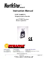
Be sure the letter “Z” and “This Side Out” are visible on the face 

of the pulse wheel after installation.

Figure 

4: 

Pulse Wheel Orientation

9                                                                    

©


DYNAPAR                                                              +1.800.873.8731 

Detail of 
surfaces that 
must be flush

Summary of Contents for NorthStar SLIM Tach SL56

Page 1: ...APAR 1 800 873 8731 791 1007 00 Rev H Website www dynapar com brand Customer Service Tel 1 800 873 8731 Fax 1 847 662 4150 custserv dynapar com Technical Support Tel 1 800 234 8731 Fax 1 847 782 5277...

Page 2: ...2 DYNAPAR 1 800 873 8731...

Page 3: ...ector 11 2 5 Returning NorthStar brand Equipment to Dynapar 11 Methods and apparatus disclosed and described herein have been developed solely on company funds of Dynapar No government or other contra...

Page 4: ...from all electrical power sources and 3 all accessory devices associates with the work area have been de energized If high potential insulation test is required follow procedures and precautions outli...

Page 5: ...s the passing magnetic pulses actuate the magnetoresistive sensor The resulting electronic signals are processed into square wave signals by the internal electronics 5 DYNAPAR 1 800 873 8731 ULatching...

Page 6: ...airs Input Voltage 5 0 to 15 0 VDC Mechanical Specifications Maximum Operational Speed 5 000 RPM Nominal Air Gap 0 019 0 008 inch Shaft Axial End Play Up to 0 045 inch maximum Enclosure Configuration...

Page 7: ...ce company Please advise us of such filing In case of parts shortages advise us immediately Dynapar cannot be responsible for any missing parts unless notified within 60 days of shipment 2 1 Motor Fac...

Page 8: ...shaft until the edge of the pulse wheel is flush with the machined recess in the encoder frame See Figure 4 We recommend you use a straight edge for this purpose For best results align the two surfac...

Page 9: ...me Insert and tighten four Phillips head screws This completes the mechanical mounting of the unit UNOTE Be sure the letter Z and This Side Out are visible on the face of the pulse wheel after install...

Page 10: ...o Connection Vcc 5 15 VDC B A Z Shield 1 2 3 4 5 6 7 8 9 10 Black Green Blue Violet Red Yellow Gray Orange Braid F B A C E D I H J G Applies only to units with index pulse capability Pinouts are for t...

Page 11: ...body and Sensor Module can be improved by smearing a sealant silicone grease etc on the neoprene seal of the connector 5 Mate connector into place on sensor mount and snap the two latches into place...

Page 12: ...31 Fax 1 847 662 4150 custserv dynapar com Technical Support Tel 1 800 234 8731 Fax 1 847 782 5277 northstar techsupport dynapar com Website www dynapar com European Sales Representative Hengstler Gmb...

Reviews: