Leaders in Pipelin
e Survey Systems
C
C
C
-
-
-
S
S
S
C
C
C
A
A
A
N
N
N
2
2
2
0
0
0
1
1
1
0
0
0
SYSTEM MANUAL Version 6.03i
42
6.8. Fault Location
There are two stages to fault location; firstly a closer inspection is required to locate the
areas of high attenuation and reduce these to smaller sections of pipeline. This is needed
to confirm if high attenuation readings are due to either a single anomaly or an area of
general degradation in the coating. If a single fault is suspected, a Close Interval Current
Only survey can be used to locate the anomaly.
6.8.1. Closer Inspection
There are occasions when a survey is proceeding and every point surveyed is producing
excellent results i.e. attenuations less than 1 mB/m. But then a section is encountered that
has a high attenuation, say 10 mB/m. If the gap between each point has been 300ft, then
we do not know where in the last 300ft the anomaly lies, so we need to use the ‘halving
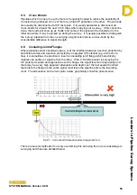
technique’ and go back to a point half way. This is demonstrated on the diagram below
(Fig 6.15), where the attenuation between points #02 & #03 is 10mB/m, so a sample is
taken at the mid-point between these two – point #04. The sample taken at this point will
reveal in which half the anomaly lies i.e. between points #02
#04 or between points
#03
#04. As the attenuation reading between points #03 and #04 is back to a normal
level (0.73mB/m) when compared to rest of the pipeline, we know that the anomaly must
lie between points #02 and #04.
Fig. 6.15 – Halving Technique
This technique of halving can be repeated again and again until the section with the
anomaly is identified, or it is shown that a length of the pipeline has generally poor coating.
However, it must be remembered that when a survey point is taken closer to the Generator
than the previous point, a change of survey direction has taken place and a negative (-ve)
distance will need to be entered into the Detector. The Detector will only know that point
#04 lies between point #02 & #03 if a negative distance is entered, otherwise point #04 will
continue on from point #03.
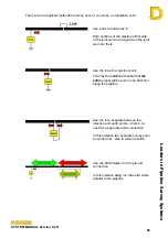
Remember that going
towards
the generator is a
negative
distance.
If GPS is being used, a
minus (–ve)
must still be used when surveying towards the
Generator. GPS has no concept of direction. When asked to enter the distance press
USE GPS
then use the
+/-
button to change bve and –ve values.
NOTE:
If chainage is being used just enter the chainage distance; there is no need for a
sign. Chainage inherently works out the position correctly.
We have now identified that the coating defect lies between points #02
#04, but from the
information above, we do not know the attenuation value between these points. To see
this we need to look at the graphs in more detail, in particular the attenuation graph. As
described in section 6.4.7 (Graphs) the operator is given the option after each survey point
to view the graphs or they can be viewed at any time for all surveys from the BROWSE
screen. Via either method, choose the attenuation graph.


