Page 5
2280 MANUAL - FORM 2280-001
MODEL 2280 SINGLE/OUTSWING
ELECTROMAGNETIC LOCK
INSTALLATION INSTRUCTIONS
4/07
705 Emmett Street Bristol, CT 06010
1-877-DynaLock www.dynalock.com
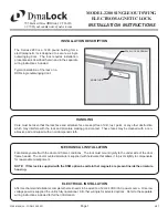
MOUNTING THE LOCK
2.
Align the Lock and Armature.
Close
and latch the door. Temporarily mount the
lock to the baseplate and verify:
a) the lock face and armature are
making full contact for the entire length
of the armature
b) the armature is horizontally centered
on the lock face
c) the door hits the frame just before the
maglock (not slamming on the lock)
If any adjustment is required, gently tap the
baseplate with a soft mallet until full contact
is achieved. Mark two baseplate corner
locations lightly with a pencil for reference.
Remove the lock from baseplate and
tighten both adjustment screws. Drive the
remaining 5 screws into the header using
the baseplate as a physical template.
Screw heads must not project above the
baseplate.
ARMATURE AND
LOCK FACE MUST
MAKE FULL CONTACT
MAGLOCK
SHOULD BE PARALLEL
HEADER
3.
Attach the Lock to the Baseplate.
With the
3/16” Hex wrench, permanently fasten the lock to
the Baseplate with the two 1/4"-20 x 1-1/4" ma-
chine screws removed earlier.
BASEPLATE
1.
Mount the Baseplate to the header.
Separate the
baseplate from the lock housing with a 3/16” Hex wrench.
Place the Baseplate against the header with the counter
sunk slots visible, and the large slot over the wire
hole. Attach the baseplate to the header at both slotted
locations using the holes drilled on page 3. Tighten the
screws just snug enough to allow for nal adjustment.
4.
Install the tamper plugs.
Gently tap the two
Anti-Tamper Plugs into the Mounting Screw Holes
using a soft faced mallet.
5.
Complete Wiring.
See separate wiring instructions.
LOCK
ANTI-TAMPER PLUG
SOCKET HEAD
MOUNTING SCREW


