


25
26
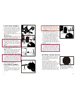
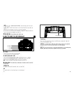
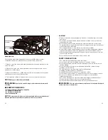
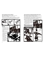
HOW TO REPLACE THE
BATTERY
1. Unscrew the two screws on the
seat and remove the seat.
2. Use a screwdriver to remove the
four screws on the battery cover.
3. Unplug the power connector
(which is connected to the
battery).
4. Carefully lift the handle on the
battery cover and remove the
dead battery together
with the battery cover
and replace it with a
new battery.
5. Secure the battery
(together with cover)
with 4 pieces of
4x16 screws, plug
the control module
connector into the
power connector and
re-mount the seat,
securing it with the
two screws removed in
step 1, above.
Battery
connector
2
3
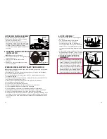
Pedal Switch Socket
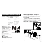
HOW TO REPLACE THE FOOT PEDAL
1. Use a flat head screwdriver to gently pry the LEFT side of foot pedal.
2. Gently remove the foot pedal.
3. Disconnect the old foot pedal from the pedal switch socket.
4. Replace and reconnect the new foot pedal to the pedal switch socket to ensure
they are connected in the correct position (see Figure 3) and then insert the right
side of the foot pedal into the foot pedal compartment first, and gently push
down on the left side of the pedal so that it snaps into place.
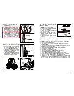
HOW TO REPLACE FORWARD-REVERSE SHIFT LEVER
1. Unscrew the two screws on the seat and remove the seat.
2. Unscrew 4 pieces of 4x12 round head screws as shown to remove the Forward-
Reverse Shifter Assembly from the vehicle body (diagram A).
3. Unplug the switch sockets from the Forward-Reverse switches (diagram B).
4. Use a flat head screwdriver to pry off the shift lever cover, and then unscrew the
4x16 mm flat head screw and remove the shift lever (diagram C).
5. Unscrew the 4 4x16 mm flat head screws and remove the shift lever assembly.
6. Replace the shift lever assembly with a new one, securing it with the 4 4x16 mm
flat head screws. Reattach the shift
lever using the 4x16 mm flat head screw
and snap the shift lever cover back into
place. Reconnect the switch sockets
with the Forward-Reverse Switches, and
reverse steps 1 and 2, above, to finish
reinstalling the shift lever.
Control Module
Connector
Power
Connector
4x12 Round
Head Screw
Battery
Cover
4x16 Flat
Head Screw
Cover
4x16 Flat
Head Screw
Shift Lever
Assembly
A
B
C
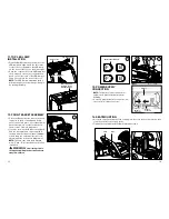
1
High
Low
Backward
NOTE:
Ensure the black switch socket plugs
into the black switch and the white switch
socket plugs into the white switch. Failure to
properly connect the plugs will result in the for-
ward and backward directions being reversed.
Shift Lever


