background image

7

.

1 PROGRAM SELECTION

The DSP 244 offers 30 user-definable program presets (U01 - U30) and up to 50 factory pre-programmed
presets (F01-F50). Altogether you have the possibility to choose from this selection of up to 80 different
programs.

CAUTION:

  A program also defines the configuration and therefore also assignment of the inputs and

outputs of the DSP 244. When changing a program you have to keep in mind that also


the wiring has to be changed, if for instance a Low-range output becomes a High-range 


output. Thus, an according message appears on the display, every time a program 
change is performed that also includes a change of the momentary configuration.

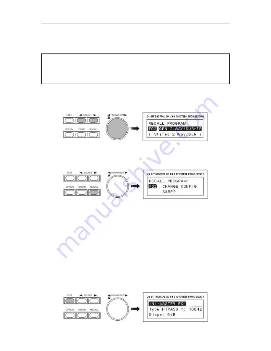
1. After pressing the RECALL key (9) you are located in the program selection menu.

2. For selecting the desired program preset you can either use the rotary encoder (10) or the SELECT

keys (5) and (6). The display instantaneously shows the new program name and the according 
configuration.

3. Activate the program by pressing the RECALL key (9). A safety dialog appears, asking you if you 

really want to activate the selected program. In case the new program’s configuration differs from the
one that had been previously selected, an additional dialog on the display informs you about this 
circumstance and about the possibility to probably change the wiring to prevent faulty operation and
the connected loudspeaker systems from being damaged.

4. By pressing the RECALL key (9) again, the program selection is being acknowledged. Pressing any 

other key cancels the selection. Depending on your action, either the new program is activated or the  
previous program stays in memory.

7.2  EDITING

The EDIT menu allows you to change the setting of parameters. A detailed description of all possible
settings is provided in chapter 8, PARAMETERS. The selection of accessible parameters depends on
the actual EDIT mode. For further information, please refer to chapter 9.5, OPERATION MODE
SELECTION.

1. Press the EDIT key (4).

2. You are located in the Edit menu. The display shows either the first menu-page of the active 

program or the last page that you made changes to, including all accessible parameters. A menu-page
always consists of the channel (IN1, IN2, IN1+2, OUT1, OUT2, OUT3, OUT4), the function block (EQ,
X-OVER, DELAY, ROUTING, LEVEL, etc.), and the corresponding parameters (e. g. Type, f, Q, Gain
in case of an EQ). The momentary selected function block or parameter is marked by a black line.

O P E R A T I O N

7-2

Summary of Contents for DSP 244

Page 1: ...OWNER S MANUAL DSP 244 24 BIT DIGITAL SOUND SYSTEM PROCESSOR 1 1...

Page 2: ...nto your outlet consult an electrican for replacement of the absolete outlet 1 Security regulations as stated in the EN 60065 VDE 0860 IEC 65 and the CSA E65 94 have to be obeyed when servicing the ap...

Page 3: ...difying Factory Preset Programs 7 5 8 PARAMETERS 8 1 8 1 Parameter Access 8 2 8 1 1 Parameter Access Table 8 2 8 1 2 Parameter Link Table 8 3 8 2 Description of Parameters 8 3 9 OPTION FUNCTIONS 9 1 9...

Page 4: ...The user can choose between two operation modes the No Edit Mode allows to simply select the required combination of loudspeaker systems from the factory preset program list Afterwards the appliance i...

Page 5: ...n blocks including their individual parameters and parameter values Additionally and depending on the actually chosen mode the display also indicates option menus status messages short operational not...

Page 6: ...output levels are needed Use the rotary controls OUTPUT 1 4 to attenuate the output levels It is not recommended to use the digital output gain control for massive attenuation since this would declin...

Page 7: ...viding that a standard MIDI interface has been installed in your PC Notebook 20 OUT 1 4 connectors These are the 4 balanced outputs of the DSP 244 The signals of these sockets supply different frequen...

Page 8: ...make the required input and output connections in advance and in accordance to the desired configuration 3 1 Balanced INPUT OUTPUT configuration For best results the DSP 244 is operated using its bala...

Page 9: ...pter 7 1 PROGRAM SELECTION You can copy this program to a user definable preset and alter the settings according to your personal preferences see chapter 7 4 STORE PROGRAMS AND PROGRAM NAMES and chapt...

Page 10: ...or configuration PROGRAM SELECTION Together with the DSP 244 you receive a listing of all available factory presets In case you are using a DYNACORD loudspeaker system that is listed just select the...

Page 11: ...tary encoder select CHANNEL EQ1 in the display Here you are able to edit the first filter of this channel Through use of the right SELECT key you are able to select the parameter Type and change its s...

Page 12: ...t channel MATCHING THE FREQUENCY RESPONSE Using the Master EQs in the input channels of the DSP 244 the PA system can be easily matched to various environmental and acoustical conditions In many cases...

Page 13: ...fic configuration which is also displayed next to the program number and program name In general all configurations offer identical signal processing blocks Five filters are available for either one o...

Page 14: ...on represents a 2 way frequency crossover with monaural sub channel and additional Fullrange output OUT 1 is the sub channel that is fed by the summed audio signals of the inputs IN 1 and IN 2 OUT 2 a...

Page 15: ...reo operation 6 4 3 Way Mono Sub Fullrange This configuration also represents a 3 way frequency crossover with additional full range output with the difference that the Sub range channel OUT 1 is fed...

Page 16: ...rcement in adjacent rooms The internal structure of the 3 Way Independent Sub Fullrange configuration is shown in the following signal flow diagram An example of a typical system configuration for thi...

Page 17: ...t channel IN 2 This structure is suitable for instance for the equalization of full range wide band loudspeaker systems or passive multi way systems The following signal flow diagram shows the assignm...

Page 18: ...the parameters of the corresponding channel The following figure shows the different menu levels and explains how to select them Initial state after power on operation Last used program with program n...

Page 19: ...guration differs from the one that had been previously selected an additional dialog on the display informs you about this circumstance and about the possibility to probably change the wiring to preve...

Page 20: ...vious parameter is selected using the SELECT keys 5 and 6 The display might show the following If needed steps 3 to 6 can be repeated as often as necessary 7 Pressing the EDIT key 4 again quits the Ed...

Page 21: ...e the rotary encoder 10 to select the desired preset location For instance the display might look like this Please proceed with step 6 if you do not want to change the program s name 4 Use the SELECT...

Page 22: ...parameters to their optimal values matching your components Afterwards your sound reinforcement system is ready for operation immediately If you want to make your own settings or re adjustments this...

Page 23: ...e following chapters IN1 MASTER EQ1 IN1 MASTER EQ2 IN1 MASTER EQ3 IN1 MASTER EQ4 IN1 MASTER EQ5 IN1 MASTER DELAY IN2 MASTER EQ1 IN2 MASTER EQ2 IN2 MASTER EQ3 IN2 MASTER EQ4 IN2 MASTER EQ5 IN2 MASTER D...

Page 24: ...STANDARD Mode 1 FULL EDIT Mode Stereo 2 Way Stereo 2 Way Mono Sub Fullrange 3 Way Fullrange 3 Way Mono Sub Fullrange 3 Way Independ Sub Fullrange 4 Way 2 In 4 Full Edit ROUTING NO NO NO NO NO NO NO Y...

Page 25: ...ges and settings Additional information about the affect of each parameter is provided through the corresponding setting example When entering the EDIT mode either the first parameter of the actual pr...

Page 26: ...quality and therefore the graph of the Hi Pass and Lo Pass filters Gain sets the degree of amplification or attenuation of the parametric EQ or the low shelving and high shelving equalizers The stepwi...

Page 27: ...ilter HISLV f 2000Hz Slope 6dB Gain 3dB 6dB 9dB 12dB Low Shelving Filter LOSLV f 200Hz Slope 12dB Gain 3dB 6dB 9dB 12dB High Shelving Filter HISLV f 2000Hz Slope 12dB Gain 3dB 6dB 9dB 12dB Hi Pass Fil...

Page 28: ...lation additionally includes the influence of the environmental temperature Temp allows you to enter a value for the momentary environmental temperature This parameter appears only when the selected d...

Page 29: ...ilter with programmable frequency quality and gain LOSLV HISLV stand for Low Shelving or High Shelving Equalizer respectively Their parameters are frequency f slope and gain The parameters of the LOPA...

Page 30: ...slope settings for the transition band are possible Together with the Q parameter this provides the possibility to program the Hi Pass filter for so called B6 alignment i e an increase in the respons...

Page 31: ...lter types generate phase responses that lead to significant level reduction in the overall audio signal at the crossover frequency This negative effect can be eliminated by inverting the polarity of...

Page 32: ...in the overall audio signal at the crossover frequency This negative effect can be eliminated by inverting the polarity of the output that carries the low frequency signal The following table provides...

Page 33: ...0 s 900000 s 0 feet 1014 feet 0 inch 12169 inch 0 m 309 m 0 cm 30910 cm 0 ms Unit ms s feet inch m cm ms Temp 20 C 60 C 4 F 140 F 20 C The Delay parameter determines the delay time of the correspondin...

Page 34: ...means that a level change of 4 dB at the input results in a level change of only 1 dB at the output provided that the input level exceeds the threshold level Attack defines the time interval after wh...

Page 35: ...drops below the threshold the audio signal s gain is processed to return to its original value This signal processing follows an exponential curve so that the volume change is appropriate for the hum...

Page 36: ...ay of the internal software revision number Press OPTION 7 to activate the option programs The last used option program appears on the display e g Use the two SELECT keys 5 and 6 to select the desired...

Page 37: ...ximately 60 dB s i e with lower signal levels the meter instruments drop slower 9 5 EDIT PROTECTION The DSP 244 offers the possibility for edit protection Once this protection mode is enabled internal...

Page 38: ...unction allows the user to select the unit for the temperature settings Temperature values are used in the master and channel delays which enables the DSP 244 to automatically include temperature re l...

Page 39: ...s transferred via the previously set MIDI transmission channel MIDI TX CHANNEL This allows to control a single or several connected DSP 244 slave units from one master All parameters and program chang...

Page 40: ...face is equipped with a 9 pole D SUB terminal strip male The pin assignment is Pins 1 8 Control contacts Pin 9 Ground You are able to connect switches rotary switches or relays which are controlled th...

Page 41: ...rameter is listed at the end of the program chart after F50 9 11 NRS 90247 RS 485 INTERFACE SETTINGS Amongst other available options retrofitting the NRS 90247 RS 485 interface in the DSP 244 instead...

Page 42: ...quency crossovers 6 12 18 24 dB oct slope Butterworth Bessel Linkwitz Riley Filters 26 parametric equalizers Low Shelving equalizer LPN Lowpass Notch switchable Hi Shelving equalizer 6 12 dB slope swi...

Page 43: ...quest recognized MIDI Byte Description F0 hex 7E 0n 06 01 F7 System Exclusive Universal System Exclusive Non real time header n MIDI Channel 0 15 7F All Channels General Information Identity Request E...

Page 44: ...ink Parser ASCII Code Line for Command Parser up to 120 Byte Checksum for DATA 7 Bit 2 s Complement End of SysEx Message Further details concerning the Command Parser ASCII Code are shown in the follo...

Page 45: ...20000 Hz TYPE THRU 6DB 12DBQ0 5 12DBQ0 6 12DBQ0 7 12DBQ0 8 12DBQ1 0 12DBQ1 2 12DBQ1 5 12DBQ2 0 LINKW12DB BESSEL12DB BUTTER12DB BESSEL18DB BUTTER18DB LINKW24DB BESSEL24DB BUTTER24DB LOPASS see HIPASS D...

Page 46: ...sembly 80449 5 screws on the bottom plate Detach the connections between the two printed board assemblies Slightly lift the printed board 80448 and carefully pull it in the direction to the front of t...

Page 47: ...ear 3 Loosen the blinding on the rear plate 2 screws on the rear 4 Install the extension kit s printed board assembly at the correct destination see figure below 5 First tighten the screws at the rear...

Page 48: ...BLOCKDIAGRAMM BLOCK DIAGRAM 10 7...

Page 49: ...FLUSSDIAGRAMM FLOW DIAGRAM 10 5...

Page 50: ...Abmessungen Dimensions in mm ABMESSUNGEN DIMENSIONS 10 6...

Page 51: ...The warranty does not cover damage that results from improper or inadequate treat ment or maintenance In case of alteration or unauthorized repairs the warranty is automatically termi nated GARANTIE L...

Reviews: