Dynacord DRM 4000 Owner'S Manual Download Page 11

4. INSTALLATION AND CONNECTIONS

4.1 General Notes

Achieving the best results possible with your DRM 4000 is only doable when making sure that all
connections are in perfect order. For operating the appliance, connect its power supply via the flat-con-
nectors on the rear panel to a 24 V DC power source. When incorporating the DRM 4000 in a PA or
intercom system, using the already present 24 V supply voltage is recommended. For including the DRM
4000 in other applications, please use the optionally available mains adapter (NRS 90257). The adapter
includes a universal input power supply with matching AMP-connectors, which directly fits  the power
supply connection (14) of the DRM 4000.

CAUTION: When establishing the power supply connection, make sure to connect the positive
conductor (24 V) to the +24V-input of the DRM 4000 and the negative conductor (Ground) to the
negative input.

 To prevent any trouble with temperature, providing sufficient ventilation is as advisable as not to operate
the DRM 4000 in environments with ambient temperatures exceeding 40°C. One Height-Unit is necessary
for rack-installation. Normally, in this case, there are no special measures, like rack blinds, for ventilation
necessary. Like with any other LF-signal processing unit, it is not recommended to install or operate the
DRM 4000 directly above or below any device that generates a massive magnetic field; e.g. power
amplifiers. In this way the risk of unwanted interference is reduced to a minimum. Before switching the
DRM 4000’s power on, make sure that all necessary connections have been established. Start  with
connecting all microphones and other audio signal sources to the inputs of the DRM 4000. Then proceed
with connecting the outputs of the DRM 4000 with the inputs of any consecutive device, e.g.  power
amplifier or DPM 4000. Make sure to also connect the direct-outs, if you are using them. 

IMPORTANT

:

- Always use high-performance, properly shielded cables.
- When establishing connections (especially input connections) make sure that the 
  connection cords do not exceed 10 m in length to prevent the loss of treble frequencies.

4.2 Input Assignment

4.2.1 MIC/LINE inputs

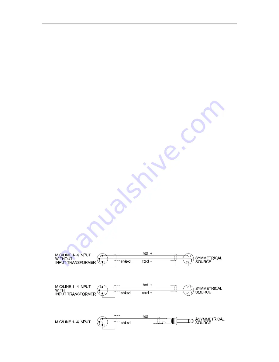
The MIC/LINE-inputs (1 and 25) are provided via XLR-type sockets. The pin-assignment for the XLR-type
plugs to be connected has to be: pin 1 = ground (shield), pin 2 = hot (+), pin 3 = cold (-). In case that the
inputs are galvanic separated via transformers (NRS 90233), do not connect the shield to the ground of
the sending device. The MIC/LINE 1-4 inputs can also be used with unbalanced signal sources. If so,
please mind the following pin-assignment: pin 1 = ground (shield), pin 2 = hot (+). For avoiding a signal
level attenuation by 6 dB, please interconnect the pins 1 and 3 inside the XLR-type plug. However, if this
causes noise interference, remove the bridge again.

The following shows examples for balanced and unbalanced pin-assignments for audio cables, like they
are commonly used with the DRM 4000.

INSTALLATI O N   A N D   C O N N E C T IONS

4-1

Summary of Contents for DRM 4000

Page 1: ...OWNER S MANUAL DRM 4000 8 IN 2 AUDIO MIXER ROUTER...

Page 2: ...et consult an electrican for replacement of the obsolete outlet 1 Security regulations as stated in the EN 60065 VDE 0860 and the CSA E60065 00 have to be obeyed when servicing the appliance 2 Use of...

Page 3: ...ation 6 2 6 3 Cascading Several Units via MIX IN and SEND 6 2 6 4 Using The Unit Together With The DPM 4000 6 3 7 SOFTWARE EDITOR DRM 4000 7 1 7 1 System Requirements 7 1 7 2 Installation Notes 7 1 7...

Page 4: ...balanced transformer optionally available 4 AUX input channels each with 2 RCA type connectors Volume and tone control Lo Hi in all input channels Signal Peak LEDs green red for monitoring the input...

Page 5: ...p it at a safe place for further reference 1 2 Unpacking and Warranty Carefully open the packaging and take out the DRM 4000 Next to this owner s manual the appliance is shipped together with three Ph...

Page 6: ...l LED lights at approx 30 dB and the peak LED at 6 dB below clipping 4 Control MIC LINE 1 4 Rotary controls for setting the volume level of the DRM4000 s corresponding MIC LINE inputs Ideally the rota...

Page 7: ...ockwise margin is possible The ducking controls are recessed mounted and can only be accessed via screwdriver to prevent faulty operation 9 Ducking indicators A B A lit ducking LED indicates that the...

Page 8: ...s These setting can be saved in the DRM 4000 For details on the pin assignment and an example of how connection is established please refer to chapter 4 4 1 17 External VCA control These control conta...

Page 9: ...d to set the input level so that it matches the desired nominal level or to match the appliance s optimum internal operation level using the gain controls In this way you obtain the optimum S N ratio...

Page 10: ...operating it for the first time please set the input controls MIC LINE 1 4 4 and AUX 1 4 7 all the way counterclockwise so that actually no audio signal is fed to the audio outputs Proceed in the sam...

Page 11: ...eld e g power amplifiers In this way the risk of unwanted interference is reduced to a minimum Before switching the DRM 4000 s power on make sure that all necessary connections have been established S...

Page 12: ...ing the SEND OUT to the MIX IN of a following unit allows comfortably cascading several DRM 4000 units which of course doubles the amount of available input channels For the case that additional input...

Page 13: ...l muting and VCA Additionally assigning individual priorities to each contact is possible This allows you to establish security relevant settings using the Priority Override function e g routing for a...

Page 14: ...he levels of MIC LINE and AUX inputs 5 2 1 Level Adjustment for MIC LINE inputs The four MIC LINE inputs are provided via balanced XLR type connectors To optimally match a signal source to a channel i...

Page 15: ...e with the highest signal level e g loudest passage in a musical piece the SIGNAL LED has to light and or blink in the rhythm of the music The AUX inputs are factory pre set to a nominal sensitivity o...

Page 16: ...input channels in the setting range between 0 dB to 40 dB The factory pre set value is 40 dB 6 2 LIMITER OPERATION The two input channels MIC LINE 1 and 2 employ an internal limiter which provides the...

Page 17: ...les with XLR type connectors Using the optionally available RS 485 remote interface NRS 90256 allows connecting the DRM 4000 to the DPM 4000 for control purposes This allows using the DPM 4000 s Desig...

Page 18: ...serial connection to the DRM 4000 7 2 Installation Notes Insert the setup disk 1 into the floppy drive A Select EXECUTE in the Windows start menu Enter the command a DRM4000 Editor exe Follow the inst...

Page 19: ...disk is possible as well The software s structure and operation is as simple as possible and mostly self explanatory To learn more about every aspect of the software please read the following parts of...

Page 20: ...inputs are engaged When the DRM 4000 is connected to your PC using the Online Control soft key allows establishing any settings in real time Change the status of the symbol bar visible invisible Chang...

Page 21: ...the input signal of the first two input channels controls the output level of the other channels Enabling or disabling the function is possible Label provides the possibility to assign individual nam...

Page 22: ...using the Online Control soft key allows establishing any settings in real time Priority The possibility for assigning priorities to the control input is provided here Priority 8 represents the highes...

Page 23: ...ntrol inputs Test Activating Test allows the simulation of setting control inputs by pres sing the according soft keys The green LED s next to the corresponding soft keys indicate the momentarily acti...

Page 24: ...S allow switching to other configurations Therefore the corresponding CONTROL INPUT needs to be connected to ground The eight CONTROL INPUTS are factory pre set to the empirically most frequently used...

Page 25: ...outputs A and B AUX inputs are summed for monaural output via the outputs A and B Stereo AUX input L is assigned to output A while AUX input R is assigned to output B this option is only available for...

Page 26: ...possibilities and corresponding factory settings Funktion Settings Factory Settings Low Cut Filter MIC LINE 1 4 ON OFF ON DIRECT OUTPUTS Kan le 1 8 PRE POST POST AUX Empfindlichkeit AUX 1 4 6 4 dBu 4...

Page 27: ...4 S1D The following diagram exemplarily shows the jumper settings of the MIC LINE 1 Low Cut filter 9 1 2 DIRECT OUTPUTS The DIRECT OUTPUTS of the eight input channels are factory pre set to POST e g t...

Page 28: ...d board assembly Use a low power soldering iron to close the corresponding Cut Solder bridge Refer to the diagram below the following table showing the Cut Sol der bridge of AUX1 R and the two setting...

Page 29: ...y lifting the front of the printed board assembly 80478 pull it to the front of the appliance so that the connectors are free of the rear panel Now you are able to remove the printed board assembly 80...

Page 30: ...d board assembly 80478 pull it to the front of the appliance so that the connectors are free of the rear panel Now you are able to remove the printed board assembly 80478 so that it is accessible for...

Page 31: ...tor 2 x Locking screws Installation Instructions NRS 90256 NRS 90258 1 Turn off the power of the DRM 4000 and open the cover plate as described before 2 Loosen the blind on the rear panel 2 screws on...

Page 32: ...2 k ohms Audio Outputs Master Output A B XLR type connectors electronically balanced transformer optionally available Nom Output Level 0 dBu 775 mV Max Output Level 21 dBu 8 7 V Output Impedance 120 o...

Page 33: ...10 2 User Configuration SPECIFICATIONS 10 2...

Page 34: ...SPECIFICATIONS 10 3...

Page 35: ...10 3 Block diagram SPECIFICATIONS 10 4...

Page 36: ...with each extension kit For detailed explanation please refer to chapter 7 Connect the DRM 4000 with your media control afterwards and utilize the contact control commands as described in the followin...

Page 37: ...via remote mind priorities Read access reads the routing of MIC LINE 1 which has been set via remote EDIT REMOTE MIC_LINE1 OVERRIDE value e g EDIT REMOTE MIC_LINE1 OVERRIDE ON EDIT REMOTE MIC_LINE1 O...

Page 38: ...10 5 Dimensions SPECIFICATIONS 10 7...

Page 39: ...covers all substantial de fects in materials and workmanship for a period of 36 months from the date of purchase Liability claims are accepted solely when a valid cor rectly and completely filled out...

Reviews: