


ASSEMBLY INSTRUCTIONS
GENERAL ASSEMBLY INFORMATION
Construction of the Mark VI is very simple when com-
pared to other kits. The printed circuit board for audio has
been preassembled to save you some of the work, and the
assembly that remains is in an open, uncluttered layout to
make wiring quick and easy. The construction time will be
several hours. It is better to work slowly and carefully rather
than concern yourself about the time.
When you unpack the kit, check off the components
against the parts list on page 23. Separate the hardware
items in an egg carton or similar container. You can identify
unfamiliar parts by checking them against the Pictorial
Diagram, bearing in mind that the drawing is necessarily
somewhat distorted for visual separation.
Have the proper tools at hand before starting construction.
The tools necessary are:
1. A pencil-type soldering iron with a 3/16" tip or
smaller of 40 to 60 watts rating, with a tip tempera-
ture of 700 to 800° F.
2. A damp sponge or cloth to wipe the tip of the iron.
3. 60/40
rosin core
solder not larger than 1/16" diam-
eter.
4. A medium sized screwdriver (1/4" blade).
5. Long nosed and diagonal cutting pliers.
6. Heavy "slip joint" pliers.
7. A single edged razor blade or inexpensive wire strip
ping tool for removing insulation.
8. Wood toothpicks.
9. Transparent or masking tape.
10. Heavy cardboard.
We do
not
recommend using a soldering gun. Not only
can a gun provide more heat than is necessary—an unskilled
user might damage printed circuit boards—but also many
users tend to make poor solder connections, simply because
they do not wait long enough for the gun to reach its operat-
ing temperature each time. Use a conventional pencil type
iron.
A good solder connection does not require a large amount
of solder around the joint. A well-made connection looks
smooth and shiny because the solder
flows into the joint
when both parts are hot enough.
There are four steps to making a good solder connection:
1. Make a good mechanical connection.
2. Heat
both
parts with the tip of the iron at the
junction.
3. Apply solder to the
junction
until it melts and flows.
4. Allow the connection to cool undisturbed.
ALL SOLDERING MUST BE DONE WITH
A GOOD GRADE OF ROSIN CORE SOLDER
Under no circumstances should acid core solder be used.
Unmarked solder, cheap solder or any of doubtful origin
should be discarded, and
separate solder fluxes should never
be used.
The warranty is voided on any equipment in which
6
acid core solder or acid type fluxes have been used. Silver
solder is not suitable. The recommended solder is 60/40
(60% tin, 40% lead)
ROSIN CORE.
Do not confuse this
with 40/60, which is harder to use.
You should realize that many of the more delicate com-
ponents are less likely to be damaged in the soldering pro-
cess if you use a hot iron for a short time, rather than a cooler
iron for a longer period. You will also make a better connec-
tion with the hot iron. If you keep the iron clean by wiping
the tip frequently, and occasionally add a small amount of
solder to the tip, it will aid the transfer of heat to the con-
nection. Do not allow too much solder to build up on the
tip though, or it may fall onto adjacent circuitry.
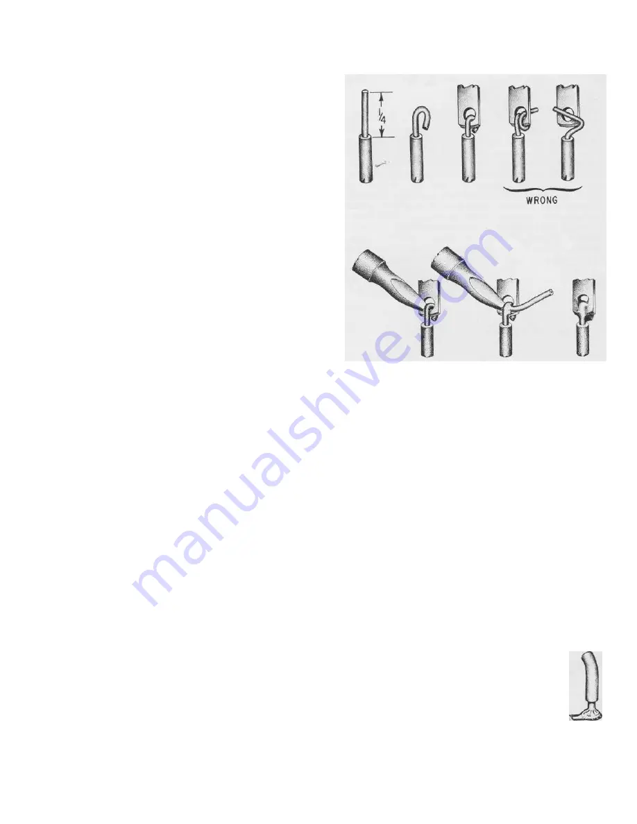
One of the best ways to make a good mechanical connec-
tion is to bend a small hook in the end of the wire, and then
to crimp the hook onto the terminal lug. The amount of bare
wire exposed need not be exactly 1/4 inch, but if it is too
long, the excess might touch another terminal lug or the
chassis. Do not wrap the wire around the lug more than one
time, as this makes the connection difficult to remove if an
error is made.
Many of the wiring steps will call for "preparing" a wire
of a certain length and color. This involves cutting the neces-
sary length of wire and stripping 1/4 inch of insulation from
each end. This is most easily done with wire strippers, but
diagonal cutters can be used if you are careful not to nick
the wire and weaken it.
When soldering a lead to a numbered, plated-
through hole on a circuit board, push the lead
through the hole first.
Do not push the wire all
the way into the hole up to the insulation.
Apply
the solder and the hot iron at the same time to
the junction of the hole and lead. The solder
should melt very quickly; it should flow easily
and fully into the hole and completely around the lead.
Remove the iron and allow the connection to cool. It is
essential
to have a smooth, shiny flow of solder from the lead
to the plated circuitry on the board.


