
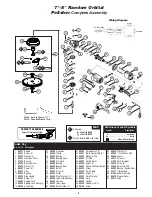

7"–
8" Random Orbital
Polisher
Complete Assembly
3
1
89371
Spindle
2
89261
Screw (4)
3
89372
Washer (4)
4
89373
Gear Box Cover
5
01036
Bearing
6
89375
Bearing Cover
7
89376
Washer (6)
8
89257
Screw (6)
9
89377
Gear
10
89378
Bearing
11
89379
Side Handle
12
89381
Screw (4)
13
89382
Spindle Lock
14
89383
Spindle Lock Spring (4)
15
89384
Snap Ring
16
89385
Gear Box
17
89386
Circlip
18
50677
Bearing
19
89387
Bearing Cover
20
89388
Armature
21
89389
Bearing
22
89390
Bearing Boot
23
89391
Baffle
24
02649
Screw (2)
25
89393
Stator
26
89394
Ring Terminal (2)
27
89353
Label (Maintenance)
28
89396
Housing
29
89397
Label (logo)
30
89398
Brush Holder (2)
31
89399
Carbon Brush (2)
32
89421
Brush Holder Cap (2)
33
89422
Magnetic Clip
34
89423
“E” Ring
35
89424
Handle Cover
36
89425
Screw (4)
37
89426
Speed Controller Switch
38
89279
Screw
39
89427
Cord Clamp
40
89283
Screw (2)
41
89281
Cord Protector
42
89428
Cord
43
89429
Handle
44
89430
Rubber Cap (3)
45
96168
Screw
46
94594
Washer (2)
47
50855
7
" Hook-Face Pad
48
94595
Spacer
49
95217
Screw (2)
50
61373
Counterweight
51
95235
Screw (3)
52
57069
Balance Shaft
53
56052
Bearing (Double Row)
54
61371
Orbital Head
55
61369
Head Assembly
56
89420
Magnet Cover
57
89412
Tape
Index Key
No. Part # Description
15
16
14
12
13
17
11
10
9
5
2
3
4
8
18
19
A . . . . . . . . . . . . . . . . . . . . .amperes
Hz . . . . . . . . . . . . . . . . . . . . . . . .hertz
. . . . . . . . . .Class II Construction
Definitions of Label Symbols
Symbol
Description
44
7
22
8
20
21
23
26
25
24
31
32
29
30
27
28
36
35
34
56
57
38
33
39
40
42
43
41
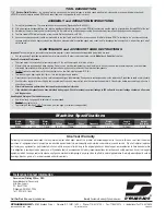
Wiring Diagram
AC 120V ~ 60Hz
Trigger
Switch
Speed
Variable
Control
Stator
Armature
37
1
6
T
A
Adhesive:
A
1
= Loctite #609
A
3
= Loctite #242
Torque:
N•m x 8.85 = In. - lbs.
KEY
7
95049
–
Hex Key Wrench
(3/16")
50679
–
Open-End Wrench
(26mm)
5.7 N•m
T
5.7 N•m
T
A
1
A
1
A
3
A
3
PREVENT PAD DAMAGE
Correct Resting Position
45
46
47
48
46
49
50
51
52
55
53
54


