background image


15 

Dymax BlueWave® LED Prime UVA User Guide 

the unit. Similar to the footswitch, if the timer/manual selector switch is in Timer Mode, the unit will power 
the LED for the time set on the timer. In the Manual Mode, the unit will power the LED for the duration of the 
remote activate signal. 

Pin 4 

 Safety Interlock In: 

A safety interlock can be connected between Pins 1 and 4. While +24V is applied 

to Pin 4, the system will allow activation of the LED. If the connection is broken, power is immediately 
removed from the LED. The safety interlock relies on the +24V signal being present on Pin 1. In addition to 
removing power from the LED, if the system is being operated in the TIMED mode, breaking this connection 

will reset the timer to zero. A second “shutter” signal will reactivate the LED for the timed duration.


Pin 5 

 Intensity In (PWM):

 This input is supplied as a means to actively control the output intensity of the 

BlueWave LED Prime UVA

 unit. It can be used to Pulse Width Modulate (PWM) the power to the LED. This 

input cannot increase the intensity over the set point of the front panel intensity adjustment, but can only 
reduce it. The front panel adjustment should be set fully clockwise to give Pin 5 the greatest range. 

A high level (+24V) on Pin 5 will turn off the LED and a low level (0V) will allow maximum LED intensity. A 
signal of 1.K Hz should be used with a duty cycle of 0 to 60%.  

NOTE: A 10% duty cycle will generate a greater intensity than a 50% duty cycle.  

This input can be used with an external controller to create any number of customized step-cure profiles or 
with an additional sensor to regulate the output. 

Output Signals 

The output signals are all opto-isolated signals. Each signal has an NPN output transistor. The emitters of all 
output transistors are tied together and connected to the PLC common on DB9 Pin 2. Each individual output 
signal line is connected to the collector of each transistor. When the transistor is turned on, this provides a 
ground to the PLC system that can be used to enable a relay coil signal to an opto-coupler. The conducting 
transistor can also function as a set of contacts that can initiate actions within the PLC. When the transistor is 

on, the signal is said to be “enabled” or “asserted”. When the transistor is off, the signal is said to be 
“disabled” or “unasserted”. The transistors have a max current rating of 30 mA, and a max power rating of 

150mW. Only positive voltages with respect to the PLC common should be used to a maximum of 24 Volts DC. 
Series-limiting resistors should be used to ensure that the max conditions are not exceeded. 

Pin 6 

 Lightguide Engaged Out: 

When a lightguide is fully inserted into the unit, an internal switch will allow 

the LED to operate. The same switch will send a signal to turn on the transistor and connect Pin 6 to Pin 2. This 
output can be used to verify the condition of the system, should an error occur, or alert a user to the failure. 

Pin 7 

 LED Powered Out: 

Pin 7 will be shorted to Pin 2 when the LED power supply is powered up and the 

set point is above a predetermined level. Pin 7 will be open with respect to Pin 2, if the LED power supply is off 
for any reason. This output can be used as go/no go confirmation that the array power supply is engaged. 
Note: Verification of LED illumination should be made visually to ensure proper operation. 

Pin 8 

 Intensity Out (PWM):

 An internal circuit monitors the current sent to the LED, and generates a PWM 

signal whose frequency and duty cycle varies with the current. Adjusting the front panel Intensity Adjustment 
Screw, or using the Intensity Input on Pin 5, will cause a change in the signal seen on Pin 8. This output can be 

Summary of Contents for BlueWave LED Prime UVA DX-1000

Page 1: ...Dymax BlueWave LED Prime UVA User Guide LED Spot Curing System Instructions for Safe Use Setup and Operation Maintenance Ordering Spare Parts and Accessories System Discontinued 1 1 2019 ...

Page 2: ...ow for 100 in line inspection and increase throughput System designs enable stand alone configuration or integration into your existing assembly line Please note that most dispensing and curing system applications are unique Dymax does not warrant the fitness of the product for the intended application Any warranty applicable to the product its application and use is strictly limited to that conta...

Page 3: ...nd Setup 10 Unpacking and Inspecting Your Shipment 10 Parts Included in the BlueWave LED Prime UVA Spot Lamp System 10 Installation System Interconnect 11 Operation 13 9 Pin Connector I O Signals 14 Input Signals 14 Output Signals 15 Cleaning and Maintenance 16 Lightguide 16 Fan Filter 17 Fuse Replacement 17 Troubleshooting 18 Frequently Asked Questions 19 Spare Parts and Accessories 20 Options Ac...

Page 4: ...et autre manuels etablir un lien avant de mettre en place et de faire marcher cette nouveau système de lampe de tache ou cette composants individuel Si vous rencontrez un problème avait n importe de questions ou si vous voudrez de nous aider avec tes suggestions ou conseillations s il vous plait contacte notre départements technique ou service client à 860 482 1010 Dymax formé professionnels atten...

Page 5: ...ction of the system Dymax assumes no liability for any changes that may impair the protection of the system Safety Recommendations Use the goggles provided or an approved face shield for eye face protection Long sleeved shirts or a lab coat are recommended for arm protection The use of UV opaque gloves will protect the hands NOTE The BlueWave LED Prime UVA emits high intensity light Never look dir...

Page 6: ...ly process There are four common questions concerns related to light curing systems UV exposure high temperature surfaces ozone and bright visible light NOTE The energy emitted from the Dymax BlueWave LED Prime UVA spot curing system is in the upper end of the UV portion of the spectrum To ensure that all safety aspects regarding operations of this equipment are addressed please review and follow ...

Page 7: ...to create simple shielding structures Sheet Metal Aluminum steel stainless steel etc Sheet metal should be coated black or black anodized to minimize reflection of UV and visible light toward operators Rigid Plastic Film Transparent or translucent UV blocking plastics typically polycarbonate or acrylic are commonly used to create shielding where some level of transparency is also desired Flexible ...

Page 8: ...e voltages of 100 to 240 VAC 50 60 Hz The BlueWave LED Prime UVA unit is comprised of an anodized aluminum housing which contains an electronic power supply circuit protection an LED assembly cooling fans a lightguide mount a lightguide safety interlock and a control PCB with connections for a remote operation system Cooling fans are provided to keep the housing and internal components of the unit...

Page 9: ...ion The following approaches may be used to validate the curing process Set Exposure Time Determine Intensity Users can specify a cure time and through empirical testing determine the intensity required to achieve a full cure As with any manufacturing process it is advisable to incorporate a safety factor Set Intensity Determine Exposure Time Users can specify light intensity and through empirical...

Page 10: ...elow If parts are missing contact your local Dymax representative or Dymax Customer Support to resolve the problem Figure 3 BlueWave LED Prime UVA Components Parts Included in the BlueWave LED Prime UVA Spot Lamp System BlueWave LED Prime UVA 1 Footswitch 2 5 mm Lightguide Models 40321 Only 3 UV Protection Goggles 4 2 mm Hex Wrench 5 Model 40321 Only Flat Blade Screwdriver 6 Model 40321 Only BlueW...

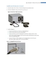
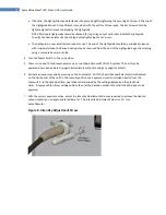
Page 11: ...otective cover from the unit s Lightguide Mount Remove the protective end caps from the Lightguide Visually inspect the two ends of the Lightguide to verify that no foreign material is present NOTE Dymax liquid filled lightguide ends can be cleaned with isopropyl alcohol to remove foreign material and outgassing deposits Fully insert the large end of the Lightguide into the Lightguide Mount on the...

Page 12: ...blade or razor knife 4 Turn the Power Switch to the on position 5 There is no need to for allow any warm up or cool down times with this LED system The unit may be powered down and powered up again immediately without causing any negative effects 6 Activate an exposure cycle by pressing on the Footswitch With the Timer Manual Selector Switch located on the front panel of the unit in the manual pos...

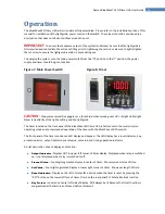
Page 13: ...end of a lightguide The timer located on the front panel of the BlueWave LED Prime UVA is factory set to the most common operating mode and recommended operation of the timer with the BlueWave LED Prime UVA The front panel of the timer contains an LED display and keypad The LED display has a reset indicator key protect indicator output indicator preset value set value and timing operation indicato...

Page 14: ...little as from the Lightguide Mount the Safety Interlock built into the assembly will terminate power to the LED Re seating the lightguide will automatically re activate it No user serviceable parts exist within the enclosure Position the curing end of the lightguide no closer than from material being cured Placing the lightguide end too close can cause the lightguide to become cloudy from vapors ...

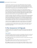
Page 15: ... The emitters of all output transistors are tied together and connected to the PLC common on DB9 Pin 2 Each individual output signal line is connected to the collector of each transistor When the transistor is turned on this provides a ground to the PLC system that can be used to enable a relay coil signal to an opto coupler The conducting transistor can also function as a set of contacts that can...

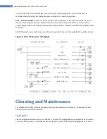
Page 16: ...age When the measured temperature drops to a lower threshold the PCB will re enable current to the LED NOTE If this fault occurs check for proper airflow into and out of the unit Also verify that the air filter is clean Figure 9 9 Pin D Connector I O Signals Cleaning and Maintenance The BlueWave LED Prime UVA was designed to operate with minimum maintenance Follow the schedule below to assure top ...

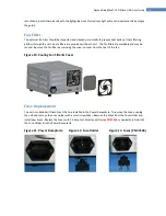
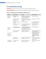
Page 17: ...and may be reused Remove the fan filter by removing the snap on cover from the rear of the fan Figure 10 Cooling Fan Filter Cover Fuse Replacement The unit is supplied with two Fuses that are installed in the Power Receptacle To remove the Fuses unplug the unit and remove the Fuse Holder with a small screwdriver Remove the Fuses from the Fuse Holder and install new Fuses Replace the Fuses with 2 0...

Page 18: ...nit fails to cure the material in the allotted time The intensity adjustment is set too low Use a radiometer Dymax ACCU CAL 50 LED to measure the output intensity Adjust the setpoint to the desired intensity The transmission loss in the lightguide is too great Compare the lightguide output against a new lightguide or use a Dymax lightguide simulator to determine the transmission loss Replace the l...

Page 19: ...lator to determine the efficiency C The intensity adjustment is set incorrectly Turn the knob fully clockwise for the maximum intensity out D The connections or signals applied to the DB9 connector are incorrect Verify that the safety and intensity input lines are not shutting down current to the LED Q Why does my BlueWave LED Prime UVA unit seem to run very hot A Replace the fan filter media on t...

Page 20: ...8 Liquid D Lightguide 5 mm x 1 M 5720 Liquid D Lightguide 5 mm x 1 5 M 5721 Liquid D Lightguide 8 mm x 1 M 5722 Miscellaneous Carry Case with Foam Inserts 1 40009 1 40010 2 40011 1 40012 Spare Replacement Parts Item Part Number Fuses Fuses F2 0 amp 37236 Fan Fan 40034 Fan Assembly 40004 Fan Filter and Holder 40460 Fan Filter Media 40008 Footswitch and AC Power Cords Footswitch 40402 Power Cord Nor...

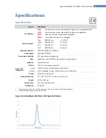
Page 21: ...pply Solid state 100 Watt Temperature Humidity 40 C maximum non condensing Timer Digital timer up to 99 99 seconds manual or timed exposure Activation Footswitch or PLC I O Port 9 Pin D sub miniature connector Signals PLC Integration Inputs 24VDC activate safety interlock output adjust Outputs LED lit lightguide inserted output setpoint over temperature Cooling Filtered fan arrangement Housing Dim...

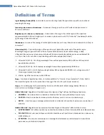
Page 22: ...om within approximately 320 280 nm 3 Ultraviolet C UV C UV of short wavelength below 280 nm typically 280 200 nm a large amount of this energy is present in sunlight 4 Visible Light that can be seen at 400 700 nm Dose Irradiance integrated over time or Irradiance W cm2 x Time s Dose Joules cm2 Note Watt is the power that gives rise to the production of energy at the rate of 1 joule J per second s ...

Page 23: ...RFORMED OR ATTEMPTED ON DYMAX EQUIPMENT WITH OUT WRITTEN AUTHORIZATION FROM DYMAX THOSE CORRECTIVE ACTIONS LISTED ABOVE ARE LIMITED TO THIS AUTHORIZATION Index Assembly and Setup 10 Cable Connections 11 Cleaning 16 Contact Information 4 Curing System Safety 6 Definition of Terms 22 Frequently Asked Questions 19 Front Panel Timer 13 Fuses 17 Help 4 I O Signals 14 Intensity Control Feature 8 Mainten...

Page 24: ...erformance testing and evaluation by offering equipment trial rental and leasing programs to assist in such testing and evaluations PN40302 MAN012 3 30 2017 Dymax Corporation 1 860 482 1010 info dymax com www dymax com Dymax Oligomers Coatings 1 860 626 7006 info_oc dymax com www dymax oc com Dymax Asia H K Limited 852 2460 7038 dymaxasia dymax com www dymax com cn Dymax Europe GmbH 49 611 962 790...

Reviews: