DXI MicroComm ICE-400 Series Installation Instructions Manual Download Page 6

ICE-400 Series Intercom Stations 

Page 6 


Document IM-ICE-400-1.1  

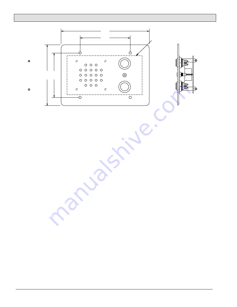
4 Mounting Holes 0.188" (3/16")

6.38"

3.63"

4.

50"

3.

2

8

"

Switch B

LED

Switch A

Minimum Opening

5.44"W x 2.88" H x 1.75"D 

3 Gang


Mounting Hole Details for 2-gang and 3-gang Intercom Stations 

Summary of Contents for MicroComm ICE-400 Series

Page 1: ...s These include i 0 1 or 2 switches These switches are mounted on the faceplate and internally terminated They can be used for call request program music selection or other functions The terminations allow the system to detect open or short line faults The switch information is multiplexed with the audio signals over a single pair of wires ii The LED stations ICE 421 and ICE 431 are used with SAB ...

Page 2: ...simplified diagram of the back view of an ICE 420 with one faceplate mounted switch is shown below The headers CN2 CN3 and CN8 CN9 are always present Connector CN2 CN3 is used to connect the printed circuit board to the faceplate components Microphone Speaker Switch B Switch A and LED Connector CN8 CN9 is used to connect the field wiring audio lines via of a 4 pin MTA 100 04 connector SPK SW SW SP...

Page 3: ...air should connect to pins 1 and 2 on a female 4 pin AMP MTA 100 series connector that plugs onto the header CN8 CN9 labeled LINE on the intercom station printed circuit board To make these connections you should use an AMP Handle Assy 58074 1 tool with a 58246 1 head The cable should be cut to length and the shield and outer jacket should be trimmed back about 1 2 inch Ensure that the shield is n...

Page 4: ...h a 4 pin MTA connectors at one end The 4 pins of the 4 pin MTA connector are connected to the header CN6 CN7 labeled Slave B of the primary station and are connected to the secondary speaker and switch pig tail wires with Marr connectors Note that the switch and speaker connections are not polarity sensitive so that the connector can be reversed The two intercom stations are assigned custom numbe...

Page 5: ...0 CUS 110 Marr Conector Marr Conector Marr Conector Marr Conector Black Green Yellow Yellow 4 wire Cable Terminated with MTA 4 Connector Two Sided Door Primary Secondary Pair with Two Separate Call Switches 5 Mounting ICM The ICE 420 and ICE 421 Intercom Stations are designed to mount in a standard 2 gang electrical box with the faceplate connected to the box by four 6 32 mounting screws The box m...

Page 6: ...om Stations Page 6 Document IM ICE 400 1 1 4 Mounting Holes 0 188 3 16 6 38 3 63 4 50 3 28 Switch B LED Switch A Minimum Opening 5 44 W x 2 88 H x 1 75 D 3 Gang Mounting Hole Details for 2 gang and 3 gang Intercom Stations ...

Reviews: