background image

Page 9 


Dipole Wires and End Insulators 

 
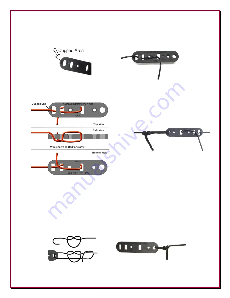
The End Insulators are installed at the far ends of the dipole wires. One on each end. Route the dipole 
wire in a serpentine manner as shown below. Note the wire enters the End Insulator at the cupped area.  


Once tuning is completed at low power, and the dipole leg wires are trimmed to length you can add an 
extra tuck in the wire end to provide even more gripping power on the dipole wires as shown below. 
Wrapping and soldering is not required. 


Attaching Rope to the End Insulators 

 
DX Engineering Double-braided Polyester Rope 

SYN-DBR

 should be secured to the Balun Mounting 

Bracket and the End Insulators (depending on your installation) using a non-slip knot.  The rope hole 
(diameter) on the Balun Mounting Bracket is 0.371" and the end insulators are 0.34".  
 
One suggestion for attaching the rope to the End Insulators is shown below.  The ends of the rope should 
be cauterized with a small flame to prevent the rope braid from fraying.   


Non-Slip Knot using SYN-DBR Double-braided Polyester Rope 

Summary of Contents for DXE-WA-BMB

Page 1: ...t Pending DXE WA BMB DXE WA BMB INS Rev 0c Shown with optional parts DX Engineering 2018 DX Engineering 1200 Southeast Ave Tallmadge OH 44278 USA Phone 800 777 0703 Tech Support and International 330...

Page 2: ...for looping or wrapping the wire ends back on to the dipole wires This allows fast and easy field adjustments of antenna length without soldering This manual does not cover all the types of resonant d...

Page 3: ...ire DX Engineering Coax Strain Relief DX Engineering Rope DX Engineering Coaxial Cable suggested Never Seez for the stainless steel hardware and DX Engineering weatherproofing materials for coaxial co...

Page 4: ...le to your home Mounting Considerations When planning the location of your antenna consideration should be given to the height location of suitable support structures and feedline positioning and leng...

Page 5: ...suggested Never Seez for the stainless steel hardware and DX Engineering weatherproofing materials for coaxial connectors Using the included Stainless Steel Hardware mount the COMTEK balun in this exa...

Page 6: ...ire fastening and fine tuning adjustment to allow for anomalies and environmental effects in your particular installation Longer length dipole legs may be required for Inverted V antennas Both of the...

Page 7: ...te where the wire enters the bracket through the cupped area Loosen the connection hardware on the COMTEK balun Wrap one of the the trimmed dipole wire ends around the balun connection point between t...

Page 8: ...ructions that are included with the strain relief for details on the assembly Connect the coaxial cable in this example DX Engineering DXE 8X with PL 259s attached to the bottom of the Balun This coax...

Page 9: ...e dipole wires as shown below Wrapping and soldering is not required Attaching Rope to the End Insulators DX Engineering Double braided Polyester Rope SYN DBR should be secured to the Balun Mounting B...

Page 10: ...Antenna Book which is available from DX Engineering Ideally the messenger line should attach to the same structure used for the dipole only above it forming at least a 30 degree angle between the dipo...

Page 11: ...le to its operating position Attached an Analyzer example Rig Expert REU AA 230ZOOM and determine the resonant point on the dipole It will probably be a bit lower than you want this is good You then n...

Page 12: ...ions such as prolonged exposure to corrosives or power surges or by the performance of repairs or alterations outside of our plant and shall not apply to any goods or parts thereof furnished by Buyer...

Reviews: