5
Internal Jumper Settings
Internal jumper JMP1 is used to select the input control function that controls the
DXE-FVC-1
.
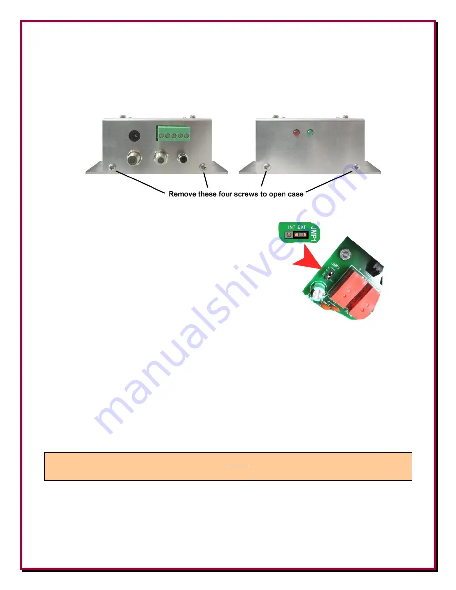
Remove the four screws holding the cover to the base to gain access to the internal jumper.
Figure 3 - 4 screws that hold the DXE-FVC-1 case together
The factory default setting has the jumper JMP1 connecting
to the two pins below EXT.
Figure 4 - Factory default setting for JMP1
When JMP1 is set to EXT, ex12 Vdc (nominal) is required for BCD input switching control.
The default jumper position, EXT, sets the
DXE-FVC-1
to respond to external source voltages of
+9 to +15 Vdc in order to control the output voltages. The
DXE-CC-8A
Control Console provides
these voltages.
If you wish to use a simple switch closure to ground on the input in order to control the output, then
change the jumper setting to INT. Control current is low (less than 100 mA). With JMP1 set to INT,
the
DXE-FVC-1
internally sources the control voltage. This allows using a 1-of-4 input switching
control scheme by grounding the appropriate input pin, which selects the desired output. Switching
can be accomplished with a simple, inexpensive SP4T rotary switch or a push-button switch
arrangement.
Note:
The
DXE-FVC-1
must be powered by 12 Vac in order to operate no matter which
way JMP1 is set.
BCD control interface systems require a 3-conductor control cable. 1-of-4 logic requires a 4-
conductor control cable. Use of the supplemental control OUT output would require a 2-conductor
cable. These conductor counts include the ground return.


