DX Engineering DXE-BFS-1 Manual Download Page 5

- 4  - 

 
The antenna can be any length between 3/8-wavelength through multiple wavelengths, although we 
recommend using lengths similar to those in the table above. In most cases, the 

DXE-BFS-1


performance is excellent even when the antenna is not cut to the ideal length. 
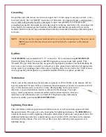


Location


Beverage antennas work well and are easy to install; you can make reasonable height changes, 
drape the antenna over tree branches, and deviate orientation by as much as 10 
degrees. Metal poles will not affect the antenna’s performance as long as the 
wire is insulated from the pole. Avoid placing the antenna near transmitting 
antennas, power lines, large metal fences, or over buried cables. Install the 
antenna wires 5-8 feet above the ground. It is not necessary to follow the 
contour of the land because small hills, ravines and ditches generally do not 
affect the antenna. Contrary to popular belief, sloping the antenna wire does 
not improve performance. The picture shown uses typical electric fence wire 
holders mounted on top of wooden posts with the beverage antenna wire 
strung through. 


Connections 

 
The 

DXE-BFS-1

 Feed Point unit has antenna terminals marked  

+

 (positive) and

 -

 (negative). Normally, the 

+

 side goes to the antenna wire 

and the

 -

 terminal goes to the antenna ground as shown in the drawing 

below. When building Beverage arrays, phase can be reversed by simply 
reversing the connections. The 

DXE-BFS-1

 also has ground-isolated 

secondaries which are essential for array construction. Do not ground the 
case of the 

DXE-BFS-1

 to the antenna ground system. 


Summary of Contents for DXE-BFS-1

Page 1: ...em DXE BFS 1 Patent Pending DXE BFS 1 INS Revision 3c DX Engineering 2017 1200 Southeast Ave Tallmadge OH 44278 USA Phone 800 777 0703 Tech Support and International 330 572 3200 Fax 330 572 3279 E mail DXEngineering DXEngineering com ...

Page 2: ...1 coaxial cable connection uses an industry standard CATV F type connector The DXE BFS 1 sets itself apart from competitive products by combining quality components and superior technology inside a compact metal housing Features 100 kHz to 30 MHz operating range Integral spark gaps built into the internal printed circuit board minimize damage from lightning Wing nut terminals eliminate soldering M...

Page 3: ...Supports can be metallic but the antenna wire must be insulated from them Specifications Operating Frequency 100 KHz to 30 MHz Input Impedance 400 500 Ω Output Impedance 30 100 Ω 75 Ω recommended Common Mode Isolation 20 30 dB feedline and antenna Power Handling 20 watts continuously or 200 watts for 5 seconds Termination Resistance 400 500 Ω Installation We strongly suggest that you read the enti...

Page 4: ... To ground the antenna run a wire from the terminal of the DXE BFS 1 to the ground rod or rods The antenna system is NOT grounded through the metal case Feedline terminals are engineered to be ground independent of the metal housing and whatever that housing is mounted on DO NOT ground the case to the antenna ground since that will connect the feedline shield to the antenna system and possibly inc...

Page 5: ...nstall the antenna wires 5 8 feet above the ground It is not necessary to follow the contour of the land because small hills ravines and ditches generally do not affect the antenna Contrary to popular belief sloping the antenna wire does not improve performance The picture shown uses typical electric fence wire holders mounted on top of wooden posts with the beverage antenna wire strung through Co...

Page 6: ...connections and follow all appropriate wiring codes for grounding where cables enter a building Bury the feed cable for 10 feet or more when approaching the feedpoint or ground the feedline shield to a separate ground rod Termination The far end of the antenna must be terminated typically at 450 to 500 Ω or the antenna will not have the optimum F B ratio Failure to terminate the antenna always res...

Page 7: ...er to test the antenna the termination and the DXE BFS 1 as a single entity Properly functioning systems will show a reasonably constant SWR value over several bands The SWR does not have to be low it is typically under 1 8 1 but should change gradually over large variations in frequency For more information about Beverage construction see ON4UN s book on Low Band DX ing ...

Page 8: ...1 connected to a radio that does not have a Receive Antenna Input This set up allows switching between a transmit antenna and the beverage antenna using the DXE RTR 1A Receive Antenna Interface Refer to the DXE RTR 1A Receive Antenna Interface manual for more information ...

Page 9: ...tact with the environment than bare wire Heavy 14 AWG stranded copper antenna wire 1000 foot bulk length spool UV resistant relaxed black PVC insulation Reduces precipitation static Long reliable life DXE RPA 1 Receiver Preamplifier 0 3 35 MHz This is the best HF low noise amplifier available The RPA 1 is optimized for 0 3 35 MHz operating range The push pull amplifier design and robust components...

Page 10: ...ool such as the DXE SNS CT1 to install the connectors Normal crimping tools or pliers will not work DXE UT KITF F Connector Coaxial Cable Prep Tool Kit This cost saving kit provides a handsome convenient carrying case complete with the DX Engineering F 6 coaxial cable prep tools and accessories It features a rugged lockable enclosure fitted with a precut foam insert with a home for each tool The D...

Page 11: ... lockout disables receive antenna during transmit mode Versatile allows inclusion of RF Preamps and other RX accessories ARR 8560 ARRL ON4UN s Low Band DXing 5th Edition The fifth edition features new and updated material Highlights include a thoroughly revised discussion of receiving antennas You ll discover how to greatly enhance their operational bandwidth In addition low signal transformers fo...

Page 12: ...riting The above warranties shall not extend to any products or parts thereof which have been subjected to any misuse or neglect damaged by accident rendered defective by reason of improper installation damaged from severe weather including floods or abnormal environmental conditions such as prolonged exposure to corrosives or power surges or by the performance of repairs or alterations outside of...

Reviews: