


7
0$5.$1'',5(&7'5,9(,167$//$7,21
,QVWDOODWLRQ3URFHGXUH
1. Unscrew cover. Keep threads clean and free from
damage.
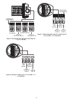
2. Switches are set at factory when in counterclockwise
position. Index marks should appear as shown (Mark
1 only). Set screws, or holes in manual cams, (#2, 4
DQGRQ&ORVHGVZLWFKHVZLOOEHGLUHFWO\DERYH
index marks.
2 Switch Unit #1 Open #2 Closed
4 Switch Unit #1, 3 Open #2, 4 Closed
6ZLWFK8QLW2SHQ&ORVHG
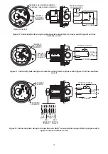
3. Attach appropriate Drive Yoke onto two pins using
DVFUHZSURYLGHG
Note:
Coupling is a special
spring temper yoke or solid metal block. Do not
attempt to fabricate your own yokes.)
4. Attach mounting bracket (127-003 is shown) to
VZLWFKKRXVLQJXVLQJÝVFUHZVSURYLGHG
5. With actuator shaft rotated to its counterclockwise
position, spread the drive yoke and slip it down
onto the square (or rectangular) part of the actuator
shaft. Attach bracket with two hex cap screws. Before
tightening screws, operate control slowly with
a wrench or power, and observe that drive shaft
and drive yoke are concentric and perpendicular
LQFRPSOHWHVWURNH$GMXVWSRVLWLRQDVUHTXLUHGDQG
tighten all the mounting screws. Check concentricity
DQGSHUSHQGLFXODULW\5HDGMXVWSHUDERYHVWHSVDV
necessary.
$GMXVWPHQW3URFHGXUH
A. Using a wrench or power, rotate the actuator shaft to
extreme clockwise position. All switches should
change to their opposite function.
B. The cam can be relocated and repositioned by
ORRVHQLQJWKHVHWVFUHZ7RDGMXVWPDQXDOFDPV
grasp cam on knurled segment of cam surface.
Simply rotate the cam on spline attached to the
VKDIW)HHOLQJRUVRXQGRIFOLFNVLQGLFDWHV
LQFUHPHQWDODGMXVWPHQWV6WRSURWDWLQJDQGUHOHDVH
pressure on cam when it is at proper actuation point.
This allows cam to engage spline. Check the circuit
to verify contact at proper point. Rotate shaft. Repeat
steps above as necessary. Lock manual cam on
spline by tightening set screw provided for additional
security.
C. Screw on cover and tighten against O-ring seal until
cover does not turn.
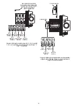
6HH 3DJHV
for wiring procedure, intrinsic safety
parameters, relevant warnings and schematics.
1.
2.
3.
4.
5.


