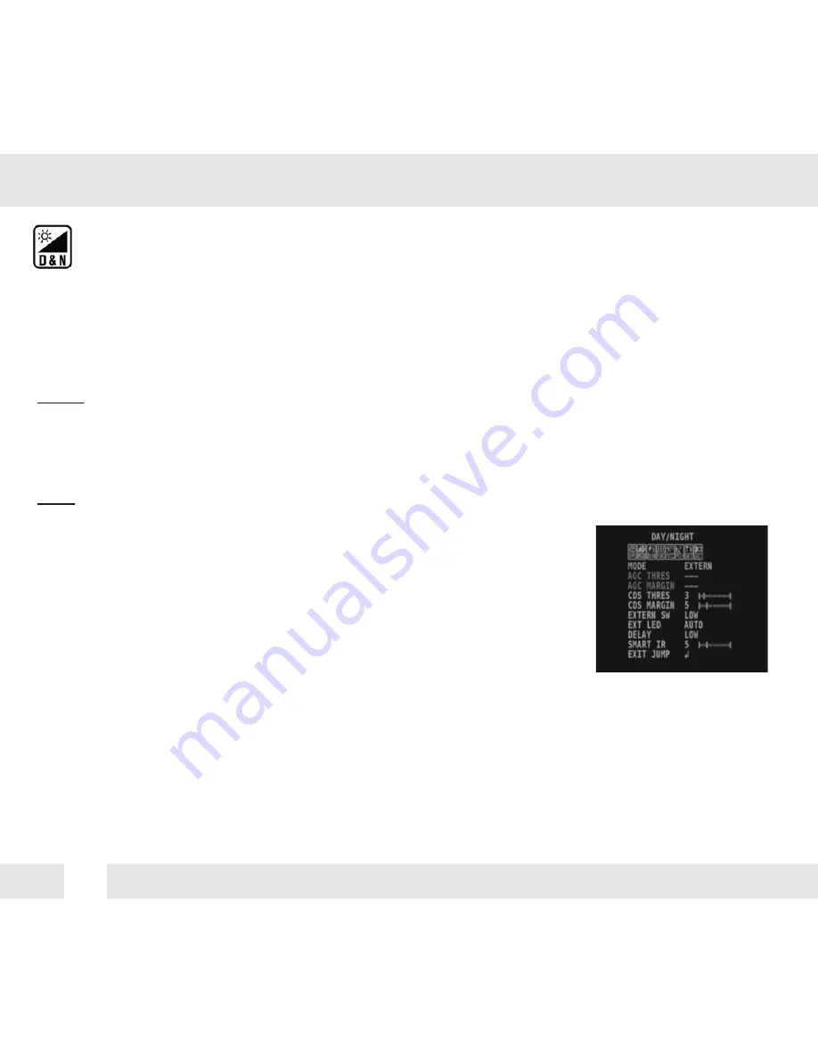
DW DWC-B6763WTIR Manual Download Page 18

18

DAY & NIGHT

AUTO / 

Day/ Night switch will be based on the AGC levels.

COLOR /   The camera always stays in day/color mode. 

B&W 

The camera always stays in night/B&W mode.

EXTERN  Day/ Night switch will be based on using IR LED lights.

AUTO: 

 - AGC Threshold: Set when the camera switches between Day & Night.

 - AGC Margin: Set the value added to the AGC Threshold. Adjust the 

   value based on the environment in which the camera is installed. If the

   margin is too low, the camera will switch from color to B/W and back. 

EXT.: 

 - CDS Threshold: Marks the light level at which the camera will switch between color and B/W.

    The lower the value, the camera will require less light (more 

    darkness) to switch to Night Mode.

 - CDS Margin: The value added to the CDS Threshold. Adjust this 

    based on the environment in which the camera is installed. If the

    margin is too low, the camera will switch from color to B/W and back.

EXT LED

AUTO /   AUTO: The LEDs are enabled/ disabled by the CDS Sensor on the LED Board.

OFF           OFF: The camera’s LEDs are disabled manually.

DELAY

Low/Mid/High    Time interval delay before switching from day mode to night mode.

SMART IR

0 ~ 20 

       Enable Smart IR and set the level. Higher values will make Smart IR stronger. 

D&N MODE

Summary of Contents for DWC-B6763WTIR

Page 1: ...015 ABOUT MANUAL Before installing and using the camera please read this manual carefully Be sure to keep it handy for future reference Analog High Definition Bullet Camera DWC B6763WTIR DWC B6763WTIR...

Page 2: ...rature may rise to high levels Cleaning To remove dirt from the case moisten a soft cloth with a soft detergent solution and wipe Mounting Surface The material of the mounting surface must be strong e...

Page 3: ...on Module OSD Menu Troubleshooting Warranty Information Specifications Features Parts and Descriptions Dimensions Inside the Box Installation Instructions Connecting to Monitors 10 Control Board 4 5 6...

Page 4: ...t IR with Intelligent Camera Sync 100 150ft Range Smart DNR 3D Digital Noise Reduction Highlight Masking Exposure HME True Day Night Mechanical IR Cut Filter Auto Sensing 24VAC 12VDC with Line Lock Se...

Page 5: ...ting Bracket Camera Module Sunshield Adjusting Screws Sunshield Cover IR Module Front Case 2 3 4 5 12 11 10 9 8 7 6 5 4 3 1 2 6 OSD Joystick Controller BNC Cable 12VDC Power Outlet RS485 Cable UTP Cab...

Page 6: ...6 DIMENSIONS IN MILLIMETERS IN 224 5 8 83 73 7 2 90 112 0 4 41 94 0 3 70 96 7 3 81 61 5 2 42 4 2 0 17 78 0 3 07 DWC B6763WTIR...

Page 7: ...7 DIMENSIONS IN MILLIMETERS IN DWC B6763WTIR650 252 0 9 9 222 5 8 76 93 5 3 68 96 7 3 8 78 0 3 07 4 2 0 16...

Page 8: ...ne Screws and 4 Dry Wall Anchors Secondary Video BNC Cable L Key DC Plug Power Cable 6 05 2015 ABOUT MANUAL Before installing and using the camera please read this manual carefully Be sure to keep it...

Page 9: ...holes to mount the bracket to a wall or ceiling 2 Pull all necessary wires through and make the proper connections 3 Use the four 4 mounting screws to install the camera on the wall or ceiling NPT 3...

Page 10: ...properly Power Connection 12VDC 24VAC Dual Voltage Auto Polarity Detection and Protection All cameras are equipped with a second video output for on site configuration CONNECTING TO MONITORS 12VDC 24...

Page 11: ...move the camera s lens cover by rotating it counter clockwise Use the Joystick to control the camera s OSD options 1 2 Joystick Controls the OSD menu Secondary Connector Video Output Connector for On...

Page 12: ...12 CAUTION ADJUSTING THE CAMERA ANGLE Do not rotate more than 360o Do not unnecessarily twist too many times 1 2...

Page 13: ...A CAM TITLE FRAME RATE FREQUENCY EXIT JUMP SAVE EXIT EXIT DEFECT DET ON LANGUAGE COLOR GAIN EXIT JUMP EXIT JUMP SENSITIVITY 0 10 DET WINDOWS EXIT JUMP POLYGON EXIT JUMP MANUAL AUTO OFF HME BLC WDR OFF...

Page 14: ...ual or FLC Flicker less mode If AUTO is selected select from the following options NORMAL Set when the camera is installed in an indoor environment DEBLUR Set when the camera is installed in an outdoo...

Page 15: ...LC is selected adjust the size nad position of the mask H POS Move the Zone position left or right The higher the number the zone will move to the right V POS Move the Zone position up or down The hig...

Page 16: ...DRC levels adjusted automatically Set the DEFOG level from LOW MIDDLE HIGH AGC AUTO GAIN CONTROL 0 10 AGC enhances the picture brightness in low light conditions A higher level AGC setting makes the...

Page 17: ...balance based on the current lighting automatically MANUAL Users can control the white balance manually by changing RED GAIN and BLUE GAIN see below C TEMP Select the color temperature for the white b...

Page 18: ...T CDS Threshold Marks the light level at which the camera will switch between color and B W The lower the value the camera will require less light more darkness to switch to Night Mode CDS Margin The...

Page 19: ...of view By default the zoom will go to the center of the camera s Field of View SHARPNESS 0 10 Sets the image sharpness The higher the number the sharper the image GAMMA 0 45 0 75 Select the desired...

Page 20: ...e higher the number the bottom side panel will move further down SENSITIVITY The smaller the movement you want to detect the higher the sensitivity value must be MOTION OSD If enabled the text MOTION...

Page 21: ...one position up or down The higher the number the zone will move down H SIZE Reset the zone s size horizontally The higher the number the right side panel will move further to the right V SIZE Reset t...

Page 22: ...pper right angle left to right POS1 Y Move the mask s upper right angle up and down POS2 X Move the mask s lower right angle left to right POS2 Y Move the mask s lower right angle up and down POS3 X M...

Page 23: ...ons 2400 4800 9600 57600 115200 bps CAM TITLE Add a name to the camera Set the title by using the OSD joystick IMAGE RANGE Image Range allows you to set the proper Black and White levels according to...

Page 24: ...g issues change the frequency value to adjust the image LANGUAGE Select from the following English Default Chinese Chinese S Japanese and Koran DEFECT DET The camera can detect and correct dead pixels...

Page 25: ...25 EXIT EXIT SAVE Exit the OSD menu after saving the recent changes INITIAL Exit the OSD menu after resetting the camera to factory default...

Page 26: ...t is connected securely Check the lens iris adjustment at the camera s OSD menu Check the power supply and make sure the camera has the proper voltage and current Check the clear dome cover and the le...

Page 27: ...ugh Friday from 9 00AM to 8 00PM Eastern Standard Time A purchase receipt or other proof of the original purchase date is required before warranty service is rendered This warranty only covers failure...

Page 28: ...low the exclusion or limitation of incidental or consequential damages or limitatons on how long an implied warranty lasts so the exclusions or limitations listed above may not apply to you This warra...

Page 29: ...ance 100ft B6763WTIR 150ft B6763WTIR650 VIDEO Image Sensor Panasonic 1 3 CMOS Active Pixels 1944 H x 1092 V Scanning System Progressive scan Frequency 60Hz 50Hz Signal Technology 2 0 Megapixel AHD Syn...

Page 30: ...ating Temperature 20 C 50 C 4 F 122 F Operating Humidity No more than 90 Non Condensing IP Rating IP66 Weather Resistant Other Certifications FCC CE ROHS OPERATIONAL CONT Digital Noise Reduction Off L...

Page 31: ...23 MEMO...

Page 32: ...5436 W Crenshaw St Tampa FL 33634 Tel 866 446 3595 813 888 9555 Fax 813 888 9262 www Digital Watchdog com technicalsupport dwcc tv Technical Support Hours Monday Friday 9 00am to 8 00pm EST...

Reviews: