background image

mmp100dn Installation Manual 


 8 


3.2.1


Fitting a Lens to the Unit 

The unit is supplied without a lens. You will need to fit a lens on the front panel of the camera (CS mount) 
before installing and connecting the unit.  

To fit a lens to the unit 

1. 

Remove the cap covering the lens mount on the front panel of the unit. 

2. 

Remove the cap on the back of the lens. 

3. 

Screw the lens into the lens mount on the unit. Make sure the lens is securely tightened on the 
unit. 

4. 

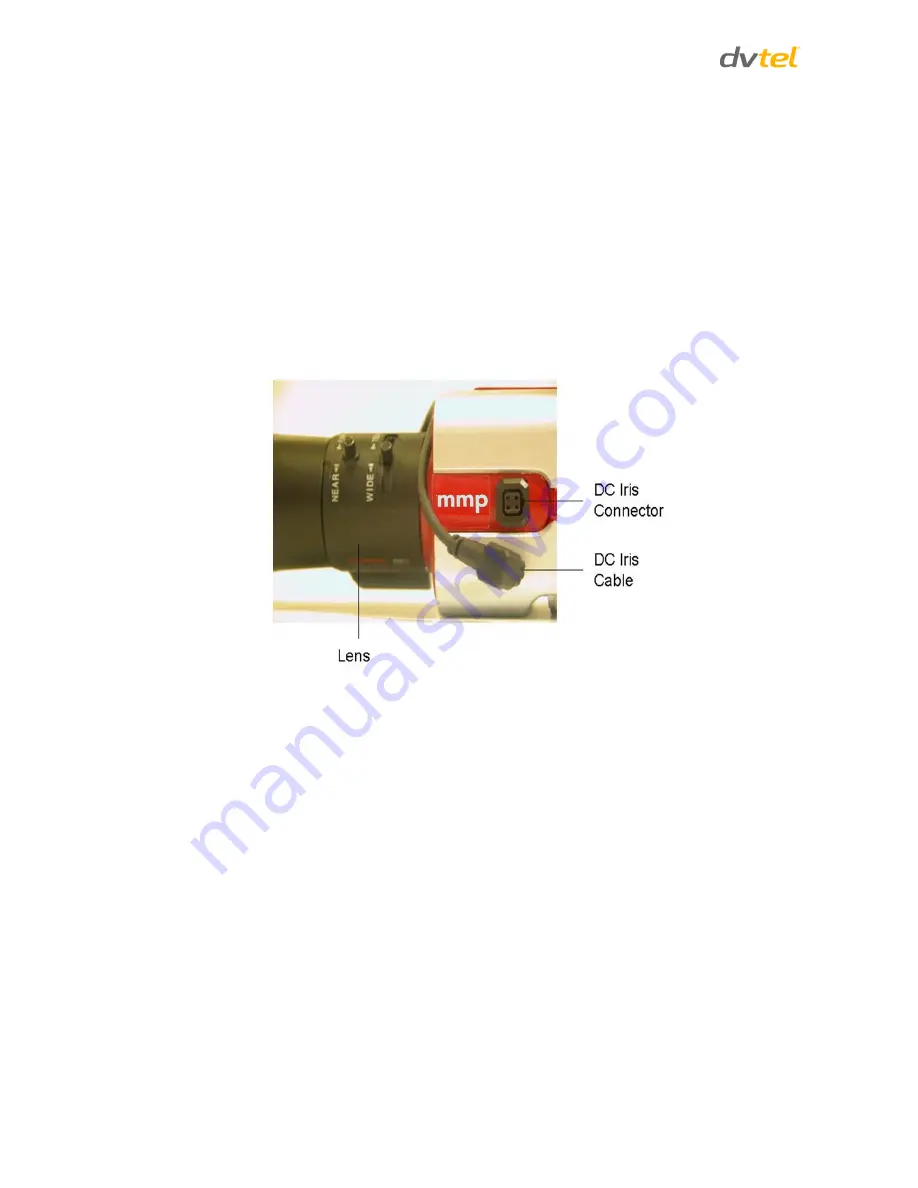
If you are using a DC Iris lens (optional), connect the DC Iris cable to the DC Iris connector on 
the side of the camera (see Figure 6). 


Figure 6: mmp100dn Camera Fitted with DC Iris Lens and DC Iris Cable 

3.2.2


Grounding the Unit  

The unit must be grounded according to local regulations and codes.  

To ground the unit 

1. 

Loosen the screw of the grounding terminal located on the back panel of the unit. See 

Figure 3: 

mmp100dn Back Panel

2. 

Attach a properly rated ground cable. Make sure the ring/spade terminal of the grounding 
cable is positioned between the toothed washers. Tighten the screw. 

3. 

Ensure that the other end of the ground cable is connected to protective earth according to 
local regulations and codes. 

Summary of Contents for ioimage mmp100dn

Page 1: ...tion Manual Rev E March 2014 DVTEL INC 65 Challenger Road Ridgefield Park NJ 07660 The contents of this guide may not be reproduced or reprinted in whole or in part without the express written permiss...

Page 2: ......

Page 3: ...t to the Network 10 3 2 5 Connecting a Microphone to the Unit 11 3 2 6 Connecting a Loudspeaker to the Unit 12 3 2 7 Connecting the Analog Video Output to an Analog Device 12 3 2 8 Connecting the Unit...

Page 4: ...igure 6 mmp100dn Camera Fitted with DC Iris Lens and DC Iris Cable 8 Figure 7 DNA Discovery Window 10 Figure 8 Connecting a Microphone to the Unit 11 Figure 9 Loudspeaker Connection to the Unit 12 Fig...

Page 5: ...Information iii Revision History Version Date Author Comments Rev D April 2013 Alan Singer Added Solo Setup Updated look and feel Rev E March 2014 Alan Singer Added DNA to section 3 2 4 Updated look...

Page 6: ......

Page 7: ...ent contains proprietary information belonging to DVTEL Inc This information is supplied solely for the purpose of assisting explicitly the licensee of the DVTEL units No part of this document content...

Page 8: ...Warning is a precautionary message that indicates a procedure or condition where there are potential hazards of personal injury or death A Caution is a precautionary message that indicates a procedure...

Page 9: ...If the intended power outlet does not support three prongs one of which is a ground contact an electrician to install the appropriate outlet NEVER remove or otherwise attempt to bypass the ground pin...

Page 10: ...wire fraying overheating etc Ensure that nothing rests on the unit s cables or power cords Ample Air Circulation Leave enough space around the unit to allow free air circulation Cabling Consideration...

Page 11: ...an automatic notification Users can define the events and location in the video of the image that can be detected with user customizable rules and positioning criteria The mmp100dn camera supports Pic...

Page 12: ...dditional package containing an 802 3af Power over Ethernet PoE injector is supplied in the same shipment Note The PoE injector is packed separately Note 1 ioimage cameras are not supplied with a lens...

Page 13: ...back panel of the unit Figure 3 mmp100dn Back Panel The back panel of the unit includes the following connections Item Description ETHERNET 802 3af PoE Port This port is used to interface with the Et...

Page 14: ...ays and additional On Screen Display OSD information Typically connected to analog video equipment such as analog video displays or to an analog video recording device or a digital video recorder DVR...

Page 15: ...des the following item Item Description DC Iris Connector For connecting the Iris Control Cable from a DC Iris lens to the unit 2 2 3 Front Panel The following image shows the front panel of the unit...

Page 16: ......

Page 17: ...e to circulate around the unit The unit is protected from direct weather conditions for example sunlight rain dust etc Caution To avoid damage from overheating or unit failure ensure that there is suf...

Page 18: ...is lens optional connect the DC Iris cable to the DC Iris connector on the side of the camera see Figure 6 Figure 6 mmp100dn Camera Fitted with DC Iris Lens and DC Iris Cable 3 2 2 Grounding the Unit...

Page 19: ...nit from a power outlet observe the following recommended AC adaptor specifications o Power Adaptor Input 110 240VAC 47 63Hz 1A o Power Adaptor Output 12 24VDC 1A 2 Connect the 12 24VDC or 24VAC power...

Page 20: ...s described below To connect a unit to the network 1 Connect a PC laptop directly to the unit using a network cable connected to the ETHERNET port located on the back panel of the unit See Figure 3 mm...

Page 21: ...ally connected on the same subnet 3 2 5 Connecting a Microphone to the Unit Using the audio splitter cable you can connect an audio input device such as a microphone to the unit in order to listen rem...

Page 22: ...Audio Output RCA connector at the other end of the audio splitter cable to the input of the audio device amplifier 3 Connect loudspeaker to the amplifier 3 2 7 Connecting the Analog Video Output to a...

Page 23: ...r NTSC 5 Click Apply to save the setting Note 1 If the video standard is changed all analytic settings will be deleted 2 Ensure that the camera and other equipment support the same video standard PAL...

Page 24: ...e COMMON lead of an external device regardless of whether the device is operated in a NORMALLY OPEN or NORMALLY CLOSED configuration NO Terminal for connecting one of a pair of wires that leads to an...

Page 25: ...anel page 3 2 Press in and release The unit resets to the previous settings 3 3 2 Reset by Removing the Power Supply The unit can be reset by turning off the power and then turning it on again To rese...

Page 26: ...Appendix 16 Appendix The appendix contains the following sections Technical Specifications page 17 Connecting Leads to a Spring Clamp Terminal Block page 19 Solo Setup page 20 Troubleshooting page 22...

Page 27: ...l Analog Video Output TV Standard Composite 1Vp p PAL or NTSC Physical Connector 1 x BNC 75 Digital Video Output IP Video Streaming MPEG 4 SP and MJPEG Maximum Resolution per Channel Channel 1 4CIF Ch...

Page 28: ...d 1A 24VDC Power Source Voltage 12 24 VDC 1A 24 VAC 50 60 Hz 1A PoE Injector 802 3af Output Voltage 48VDC 0 4A Power Consumption 9W Physical Dimensions Dimensions mm 72 x 60 x 149 mm W x H x D Dimensi...

Page 29: ...To connect a wire to the spring clamp terminal block 1 Strip the insulation form the end of each wire that is to be connected to the terminal block Approximately 1 cm 2 54 of wire should be exposed 2...

Page 30: ...trol icons are available on the Solo Setup keypad Icon Function Notes Start Recording Starts recording and browses to destination folder where the clip will be saved Stop Recording Stops recording Bro...

Page 31: ...ons in the HTML Edition Units User s Guide 8 Click Browse to load the clip from the folder where it is saved 9 Use the Play Pause Fast Forward and Rewind buttons on the Solo Setup keypad to explore th...

Page 32: ...Connecting the Unit to the Network The IP address responds to a ping on the network from the workstation but does not show in the DNA Application Disconnect the unit s Ethernet 10 100 port or turn th...

Page 33: ...tings Refer to the HTML Edition Units User s Guide for details Refresh your browser screen F5 Check that the bandwidth and bit rate settings of the network are set properly Check that other processes...

Page 34: ...per rule for activating a relay output has been defined in the unit or activate it manually Refer to the HTML Edition Units User s Guide for details Check the relay output wires are connected securely...

Page 35: ...x 44 0 1494 446928 info uk dvtel com INDIA AND SAARC GULF REGION DVTEL India Pvt Ltd 303 SSR Corporate Park Mathura Road Faridabad 121002 Haryana India Tel 91 129 431 5031 Fax 91 129 431 5033 info asi...

Reviews: