background image

2-1

2

1

3

4

5

2

I

A

Overview

This chapter provides a detailed overview of the Pronto3 hardware. The 
system will be shown in a front and a rear view and all its parts and con-
nectors will be described. For explanatory reasons the section about the 
rear also contains some further information about the digital video in- 
and outputs.

Summary of Contents for Pronto3

Page 1: ...Pronto3 Hardware Guide Version 1 0 Digital Disk Recorder Pronto3 Hardware Guide ...

Page 2: ......

Page 3: ...2 1 3 I A 4 5 Pronto3 Hardware Guide Introduction Overview Installation Operation Maintenance Appendix Index ...

Page 4: ... no event shall DVS Digital Video Systems AG be liable for any dam ages whatsoever including without limitation any special indirect or consequential damages and damages resulting from loss of use data or profits or business interruption arising out of the use of or inability to use the hardware software and or manual materials Those parts of this documentation that describe optional software or h...

Page 5: ... 49 511 630070 E mail info dvs de Internet http www dvs de Phone 49 511 67807 25 Fax 49 511 67807 31 E mail support dvs de U S Headquarters DVS Digital Video Inc 300 East Magnolia Boulevard Suite 102 Burbank CA 91502 USA Phone 1 818 846 3600 Fax 1 818 846 3648 E mail info dvsus com Internet http www dvsus com E mail support dvsus com ...

Page 6: ......

Page 7: ...is registration form and send or fax it to the address on the right You may also use our online registration form which can be accessed from the following internet page http www dvs de support further support html Customer Name Company Contact Address Phone Fax Vendor Pronto3 Serial No Remarks Connected devices Brand and type of edit controller VTR color grading system etc PLEASE SEND TO DVS Krepe...

Page 8: ......

Page 9: ...w of the Front 2 2 2 1 1 The Front of the System 2 2 2 1 2 Operation Items 2 3 2 1 3 HDD LEDs 2 4 2 1 4 Faceplate 2 5 2 1 5 Hard Disk Array 2 6 2 1 6 DVD Drive 2 7 2 2 Overview of the Rear 2 9 2 2 1 The Rear of the System 2 9 2 2 2 Digital Video I Os 2 10 2 2 3 Power Supply 2 11 2 2 4 Main Connector Panel 2 13 2 2 5 ATX Connector Panel 2 14 2 2 6 Slot Panel Connectors 2 15 3 Installation 3 1 ...

Page 10: ... Closing the Casing 5 6 5 3 Fan Maintenance 5 7 5 4 Power Supply Maintenance 5 10 5 5 Removal of the Faceplate 5 12 A Appendix A 1 A 1 Troubleshooting A 2 A 2 Technical Data A 4 A 2 1 General Technical Data A 4 A 2 2 Dimensions A 5 A 3 Hardware Specifications A 6 A 4 Video Rasters A 8 A 5 Signal In and Outputs A 9 A 6 Packing Instructions A 12 A 7 Conformity Declarations A 14 A 7 1 RoHS Compliance...

Page 11: ...re up to 16 different channels of audio can be in or output by the Pronto3 and all audio data can be accessed and processed with the software as easily as the video material The Pronto3 provides enough intrinsic power to accept material from cameras telecines or VTRs In a studio environment the Pronto3 con nects to high resolution cameras enabling the capturing of footage to gether with an immedia...

Page 12: ...e Frames are skipped according to the Variframe flag Works in 720p 1080i 1080p and 2K formats Pronto3 Special Raster Formats Some standard and non standard for mats including Slow PAL 625i 24 and Eureka 1980 1152i 25 Pronto3 Teletext VBI 335 Enables capture and play of teletext in formation in line 335 of 625 lines rasters Pronto3 Dual Link SDI Dual link SD HD SDI for input and out put for the Pro...

Page 13: ...ad here to and some important notes that you should observe Chapter 2 This chapter gives a front and rear overview of the system detailing all items connectors and interfaces Additionally it contains some fur ther information about the digital video in and outputs Chapter 3 Describes the hardware installation of the Pronto3 Chapter 4 Explains how to operate the Pronto3 i e how to start and shut do...

Page 14: ...ollowing typographical conventions will be used in this documen tation y Texts preceded by this symbol describe activities that you must per form in the order indicated Texts preceded by this symbol are parts of a list Texts preceded by this symbol are general notes intended to fa cilitate work and help avoid errors You must pay particular attention to text that follows this symbol to avoid errors...

Page 15: ...nternal components of the Pronto3 when ever possible Computer hardware contains components that are sensitive to changing voltages Connecting or disconnecting the Pronto3 to or from peripheral hardware while any of them is switched on may damage the hardware Switch off all peripheral hardware before connecting or disconnecting anything Use store and transport the Pronto3 only in compliance with th...

Page 16: ... period you have to keep the original packing and use it in case of transportation Environmental Conditions For error free working and a long service life the Pronto3 needs some basic environmental conditions Do not expose the Pronto3 to sources of heat such as direct sun light or a radiator Do not cover or obstruct the ventilation holes of the system front as well as rear When installing the DVS ...

Page 17: ... DVS product in it in case of a product return If the customer is not satisfied with the repair DVS will have the option to either attempt a further repair ex change the product or refund the purchase price This warranty does not cover Products not developed by DVS Digital Video Systems AG Products not used in compliance with the safety instructions detailed in section Safety Instructions on page ...

Page 18: ...g the hardware software and or BIOS settings may lead to a loss of perfor mance or may even render the system unusable Re configur ing the system anew is in most cases a lengthy procedure Do not change any of the settings unless you are absolutely sure of what you are doing and what the results would be Your DVS system has been tested thoroughly and is very reli able However because of the vast am...

Page 19: ...verview of the Pronto3 hardware The system will be shown in a front and a rear view and all its parts and con nectors will be described For explanatory reasons the section about the rear also contains some further information about the digital video in and outputs ...

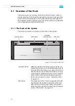
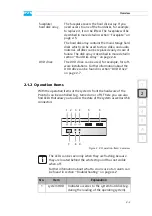
Page 20: ... of the front operation items With the operation items the system can be con trolled e g turned on or off Additionally they of fer some LEDs that allow you to assess the state of the Pronto3 as well as USB connectors for an easy connectivity to additional devices such as memory sticks Further information about the operation items can be found in section Operation Items on page 2 3 HDD LEDs The upp...

Page 21: ...ontains the main storage hard disks which can be used to store video and audio material All disks can be replaced easily in case of failure The disk array is described in more detail in section Hard Disk Array on page 2 6 DVD drive The DVD drive can be used for example for soft ware installations Further information about the DVD drive can be found in section DVD Drive on page 2 7 The LEDs can be ...

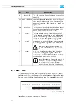
Page 22: ...ial bus at the front offer you the possibility to connect other devices such as memory sticks easily 7 power The power switch turns the system on or off The respective state of the system will be indi cated by the DVS logo in the middle of the face plate see section Faceplate on page 2 5 8 reset Resets your system and initiates a warm reboot Use a thin pointed object to press this button Save your...

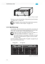
Page 23: ...covers the hard disks of the hard disk array Figure 2 5 Overview of the faceplate The faceplate is built with an integrated backlit DVS logo which indi cates the state of the system i e its power on status If the DVS logo is illuminated the power is turned on if not the power is turned off The top side of the faceplate is hinge fastened while its bottom side is fixed with magnets If you need acces...

Page 24: ...s it is normally RAID protected Once the faceplate is lifted see section Faceplate on page 2 5 you have access to the hard disk array Figure 2 7 Hard disk array The faceplate can be removed for transport reasons see sec tion Removal of the Faceplate on page 5 12 Further information about RAID can be found in section In troduction to RAID Data Protection on page 5 2 The system hard disk is not amon...

Page 25: ...ier The disk carriers hold each one hard disk of the array The hard disks are mounted to the disk carriers with several screws normally located at the sides of the carriers lever Once the lever is unlocked with the opener it can be used to pull the disk carrier and its hard disk out of the system opener Unlocks the lever and with it the disk carrier LED disk power Shows whether the disk of the dis...

Page 26: ...ending on the type of drive delivered to you the DVD drive may also provide burning capability DVD tray The DVD tray holds the CD or DVD DVD eject Opens the DVD tray when the system is turned on emergency eject You can open the DVD tray with the system cut from power Insert a thin pointed object into the emergency eject hole Then the DVD tray opens DVD tray DVD eject emergency eject ...

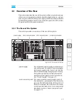
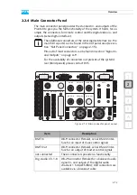
Page 27: ...sists of several indepen dent power supply units Even if one fails the others will still supply enough power to keep the system operational Further information about the power supply can be found in sec tion Power Supply on page 2 11 main connector panel The main connector panel provides most of the standard in and outputs of the Pronto3 to give you the full functionality of the system It holds fo...

Page 28: ...video ports mostly labeled A single link For YUVA you will need two channels A for YUV and B for the key signal With RGB you will always need two channels A and B dual link The Pronto3 provides two ports for an input as well as an output at the rear of the system Currently the SD only ports provide no functionality and are reserved for future use ATX connector panel On this panel you can find the ...

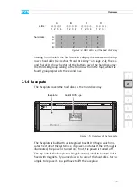
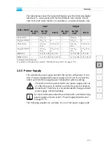
Page 29: ...ode Input Output SD only Port1 1 Reserved for future use SD HD Port2 2 Located on slot panel see section Slot Panel Connectors on page 2 15 Port B SD only Port1 SD HD Port2 Port B YCbCr 4 2 2 Y Cb Cr Y Cb Cr YCbCrA 4 2 2 4 Y Cb Cr A Y Cb Cr A YCbCr 4 4 4 Y Cb Cr Cb Cr Y Cb Cr Cb Cr YCbCrA 4 4 4 4 Y Cb Cr Cb Cr A Y Cb Cr Cb Cr A RGB 4 4 4 G R B R B G R B R B RGBA 4 4 4 4 G R B R B A G R B R B A The...

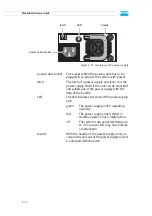
Page 30: ...ut of the power supply with the help of the handle LED The LED indicates the state of the power supply unit green The power supply unit is operating normally red The power supply unit is either in standby mode or has a malfunction off The system is disconnected from pow er In rare cases this may also indicate a malfunction handle With the handle of the power supply unit you can pull the unit out o...

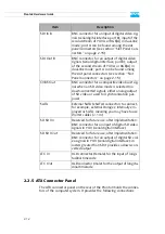
Page 31: ...n be found in section Signal In and Outputs on page A 9 For the availability of connectors not present at the system s rear blind panels please contact DVS Item Description RMT In DB 9 connector female serial RS 422 inter face for an input of slave control signals RMT Out DB 9 connector female serial RS 422 inter face for an output of master control signals not connected These connectors provide n...

Page 32: ...anel Connectors on page 2 15 CVBS Out BNC connector for a composite video burst sig nal when an SD video mode is selected no down converted signal either analog output of SD video or used for synchronization pur poses SATA External SATA eSATA connectors to connect for example external storages internally em ployed as SATA meaning you may have to use shorter cables 1 m SD SDI In Reserved for future...

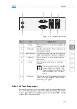
Page 33: ...ct a mouse to the system 2 COM port RS 232 connector for the connection of se rial interface devices 3 4 LAN 1000 Mb Gigabit Ethernet 1000 Base T connection ports to connect the system to a network 5 keyboard PS 2 connector to connect a keyboard to the system 6 VGA DB 15 connector female to connect a monitor If an extra graphic card is installed in your system see section Slot Panel Connectors on ...

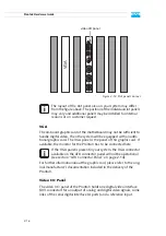
Page 34: ... the delivery of the Pronto3 Video I O Panel The video I O panel of the Pronto3 holds one digital video interface DVI connector for an output of analog and digital video signals some links of the serial digital interface A ports and a reference input The layout of the slot panel area on your system may differ from the figure above The position of the individual slot panels may vary and additional ...

Page 35: ...ctor for an input of digital video signals serial digital interface port A either input of YUV in single link or first stream of YUVA RGB A in dual link mode HD SDI OUT BNC connector for an output of digital video signals serial digital interface port A either output of YUV in single link or first stream of YUVA RGB A in dual link mode Ref In BNC connector for a synchronization of video sig nals i...

Page 36: ...2 18 Pronto3 Hardware Guide ...

Page 37: ...east 1024 768 pixels default manufacturing setting y Connect any other peripheral computer and video equipment For an overview of the panels and connectors at the system s rear see section Overview of the Rear on page 2 9 y Connect the power cable s to the system The Pronto3 hardware is now properly installed and you can switch on the system as described in section Starting the System on page 4 1 ...

Page 38: ...3 2 Pronto3 Hardware Guide ...

Page 39: ...may start the Pronto3 at any time To start the system perform the following y Press the power switch briefly to turn on the system The system will be started and the DVS logo in the middle of the face plate lights up As with any standard computer after initial booting the system begins to load the installed operating system When the oper ating system has finished its loading you can begin to work ...

Page 40: ...ly you can initiate a fast shut down by pressing the power switch briefly Some settings will be saved and afterwards the system turns off With the operating system not completely loaded If the operating system is not completely loaded perform the follow ing y Shut down the system by pressing the power switch until the sys tem turns off The system will then shut down immediately After a shut down w...

Page 41: ... that you can perform on your own For each work a detailed procedure description is given If you experience trouble with the system that cannot be resolved with the work described here or the section Troubleshooting on page A 2 please contact your local vendor or DVS directly ...

Page 42: ...th a broken disk an operation can still be continued and once the failed disk has been replaced the missing data can be recovered easily The main storage of the Pronto3 comprises up to 16 hard disks and the data is striped across these hard disks Additionally it provides up to two RAID controllers that each connects a set of eight hard disks The RAID controllers are independent RAID 5 systems and ...

Page 43: ...ollowing If a second disk within the same disk set fails your data will be unrecoverable An alarm can be caused by a number of reasons Please refer to section Troubleshooting on page A 2 first for further de tails about what to do in case of an alarm If a hard disk of the hard disk array fails the alarm will be sounded by a RAID controller It cannot be switched mute with the mute button of the ope...

Page 44: ...s will cause the lever to come out of the disk carrier so that it pro trudes a little from the rest of the front y Take the lever and turn it more to the left 2 until it cannot be moved further Figure 5 2 Pulling out the lever This takes the hard disk installed in the disk carrier out of the system s interfaces inside y Once the interface connection inside the system is severed you can pull the di...

Page 45: ...om the pushing y Then simply close the lever until it snaps back in place which as a result will slide the carrier completely back in Once the faceplate of the DVS system is back in place the replacement of the hard disk is finished After several minutes the replaced hard disk will be automatically recognized by the system Then the rebuild of the data will be initiated on its own Once the system h...

Page 46: ...igure 5 3 Removal of the cover of the casing Once the cover is slid backward it can be taken off the system 5 2 2 Closing the Casing After finishing your task at hand you have to close the casing of the Pronto3 system again For this perform the following y Simply put the cover back on and slide it into place until it locks y Afterwards reconnect the power cords The system your are working on opera...

Page 47: ...of the system as described in section Opening the Casing on page 5 6 An alarm can be caused by a number of reasons Please refer to section Troubleshooting on page A 2 first for further de tails about what to do in case of an alarm The system your are working on operates with voltages that can be hazardous to your health Never work on the system or access its interior with the power cable s being p...

Page 48: ... this perform the following y Press the latch of the respective fan module towards the front of the system 1 y With the locking mechanism released pull the fan module up and out of the system 2 Figure 5 4 Removal of fan module This will sever the connection of the fan to the system Testing the fans is possible only with an opened casing and the power turned back on Once the power cables are plugge...

Page 49: ...ed fan module into the system y Next close the casing of the system as described in section Closing the Casing on page 5 6 With the last step finished you have successfully replaced the defective fan module Once the system is turned on no alarm should be sounded anymore Only use original manufacturer spare parts Other spare parts might damage your system See to it that the fan module plugs properl...

Page 50: ... or lit in red y Next unplug the power cord from this power supply unit y Take the handle of the respective unit and press the unit s latch to the right to unlock it y Then pull the unit at its handle out of the power supply y Change the power supply unit against a new and operable one y Slide the new unit into the power supply until it clicks into place The system can be operated with one power s...

Page 51: ...source the power cord to the newly installed power supply unit y After that check the LED indicating the status of the power supply unit If it is lit up in green the unit is working properly With this the power supply unit has been replaced successfully ...

Page 52: ...able with a jack connection that supplies the DVS logo of the faceplate with power y Unplug the jack connection y Next hold tight the faceplate and remove the hinge wires as indi cated in the following figure Figure 5 5 Removing the hinge wires Afterwards the faceplate can be taken off The system must be operated only with the faceplate installed to ensure electromagnetic compatibility To reassemb...

Page 53: ...A 1 2 1 3 4 5 I A A Appendix This chapter first gives some hints how to resolve irregularities during operation After that technical data and general information about the Pronto3 are provided ...

Page 54: ...s in a RAID protected storage can prove diffi cult If you are able to detect the worn disk s replace them as de scribed in section Hard Disk Main tenance on page 5 2 Otherwise contact the DVS service department An alarm is sounded and the alarm LED is lit The alarm can be switched mute with the mute button A fan has failed Check whether a fan has failed as described in section Fan Mainte nance on ...

Page 55: ...ection Power Supply Mainte nance on page 5 10 An alarm is sounded and the alarm LED is off The alarm cannot be switched mute with the mute but ton OR At start up the sys tem is not able to ini tialize a disk set i e one or more hard disks are not recog nized by the system A hard disk or a hard disk carrier got loose jammed e g after transport or is not mounted correctly Shut down the system as des...

Page 56: ...air is conducted to the rear of the rack and properly vented away Weight approx 45 kg Environment also during transport No exposure to heat No exposure to strong electric or magnetic fields No vibrations shocks allowed Operating temperature Maximum 10 30 C 50 86 F Optimum 15 25 C 59 77 F Storage temperature 0 50 C 32 122 F Humidity 10 80 non condensing at all times Air Dust free Power consumption ...

Page 57: ...rude from the rear plug safety l minus j usually plus 150 mm However this amount of space depends on the type of connectors used Figure A 1 Measured dimensions a 176 mm g 142 mm b 139 mm h 50 mm c 37 mm i 58 mm d 25 mm j 655 mm e 455 mm k 687 mm f 480 mm l 805 mm plug safety side rear 21 00 199 10 220 10 25 30 455 30 480 60 g 49 00 56 00 660 10 688 10 720 10 d e f a b c h i j k l g ...

Page 58: ...gital 4 2 2 8 10 bit Serial Digital 4 4 4 8 10 bit Dual Link 2 1 BNC 2 BNC 1 BNC 2 BNC Reference Input Output Analog Reference Genlock 1 BNC H V via DVI Audio Input Output Embedded Audio 8 Digital Stereo Chan nels 1 BNC via Video In 1 BNC via Video Out AES EBU 4 Digital Stereo Channels 1 DB 25 XLR via breakout cable 1 DB 25 XLR via breakout cable Timecode Input Output Longitudinal LTC 1 XLR female...

Page 59: ...mat Uncompressed YUV 4 2 2 YUVA 4 2 2 4 RGB 4 4 4 RGBA 4 4 4 4 all in 8 10 122 bit user selectable Internal Processing Color space conversion User definable LUT Frame repetition Input raster detection Audio Formats 48 kHz 20 24 bit 1 In SD video modes only 2 Optionally available Table A 1 Pronto3 specifications cont ...

Page 60: ...TSC HR 525 960 486 16 9 625i 25 PAL HR 625 960 576 16 9 720p 23 976 24 25 29 97 30 50 59 94 60 71 928 72 750 1280 720 16 9 1035i 29 97 30 1125 1920 1035 16 9 1080i 23 976 24 25 29 97 30 1250 1920 1080 16 9 1080p 23 976 24 25 29 97 30 47 952 48 50 59 94 60 1125 1920 1080 16 9 1080psF 23 976 24 25 29 97 30 1125 1920 1080 16 9 2048p 23 976 24 1125 2048 1080 2 1 2048p 24 1600 2048 1536 4 3 2048p 24 16...

Page 61: ...I Pin No Signal Pin No Signal Pin No Signal 1 TX_2 9 TX_1 17 TX_0 2 TX_2 10 TX_1 18 TX_0 3 GND 11 DVI_CLK_B 19 DVI_CLK_B 4 TX_4 12 TX_3 20 TX_5 5 TX_4 13 TX_3 21 TX_5 6 DDC_CLK 14 5V 22 GND 7 DDC_DAT 15 GND 23 TX_CLK 8 ANALOG_VSYNC 16 HP_DETECT 24 TX_CLK C1 ANALOG_RED C3 ANALOG_BLUE C5 GND C2 ANALOG_GREEN C4 ANALOG_HSYNC external view female on interface male on cable 1 9 17 3 11 19 2 10 18 4 12 2...

Page 62: ...udio OUT CH 5 6 3 Audio OUT CH 5 6 16 GND 4 Audio OUT CH 3 4 17 Audio OUT CH 3 4 5 GND 18 Audio OUT CH 1 2 6 Audio OUT CH 1 2 19 GND 7 Audio IN CH 7 8 20 Audio IN CH 7 8 8 GND 21 Audio IN CH 5 6 9 Audio IN CH 5 6 22 GND 10 Audio IN CH 3 4 23 Audio IN CH 3 4 11 GND 24 Audio IN CH 1 2 12 Audio IN CH 1 2 25 GND 13 external view female on interface male on cable 1 13 25 14 ...

Page 63: ... SATA eSATA Connector RMT In RMT Out Pin No Signal Pin No Signal 1 1 2 TX_D_CON 2 RX_C_CON 3 RX_D_CON 3 TX_C_CON 4 GND 4 GND 5 5 6 GND 6 GND 7 TX_D_CON 7 RX_C_CON 8 RX_D_CON 8 TX_C_CON 9 9 Pin No Signal Pin No Signal 1 GND 5 RX 2 TX 6 RX 3 TX 7 GND 4 GND external view female on interface male on cable 5 9 1 6 7 1 external view female on interface male on cable ...

Page 64: ...n Otherwise the warranty will be void In any other case if you do not have the original packing any more use a similar structured packing for transportation DVS can not be held liable for damages due to transportation Fragile Avoid shocks or vibrations For longer distances use a lifting truck Keep dry Figure 1 Figure 2 a b c Video System Front Rear Box A Box A Box A Box A ...

Page 65: ...A 13 2 1 3 4 5 Appendix I A Figure 3 Figure 4 Figure 5 a b c Box A Box B Box B Box B Box B Box B ...

Page 66: ...vices are manufactured in compliance with this directive A 7 2 EC Declaration of Conformity CE Marking DVS Digital Video Systems AG herewith declares that the following product s according to the provisions of the mentioned EC Directives including their relevant revisions at the time of this declaration is are in conformity with the detailed standards or other normative docu ments Pronto3 EC Direc...

Page 67: ...nd used in accordance with the instruction manual may cause harmful interference to radio communications Op eration of this equipment in a residential area is likely to cause harmful interference in which case the user will be required to correct the inter ference at his own expense Note Connecting this device to peripheral devices that do not comply with Class A requirements or using an unshielde...

Page 68: ...A 16 Pronto3 Hardware Guide ...

Page 69: ... conformity declaration 1 7 A 14 connectors 2 9 ATX connector panel 2 10 2 14 DVI 2 17 labeling 2 10 main connector panel 2 9 2 13 naming conventions 2 10 slot panels 2 10 2 15 USB 2 4 conventions naming of connectors 2 10 typographical 1 4 CVBS Out 2 14 D F data loss 2 6 data protection 5 2 DB 25 connector A 10 DB 9 connector RMT In A 11 RMT Out A 11 declaration of conformity 1 7 A 14 Digital Aud...

Page 70: ... 5 J L keyboard 2 15 3 1 labeling of connectors 2 10 LAN 2 4 2 15 latch 2 12 LEDs alarm 2 4 5 7 A 2 A 3 disk activity 2 7 disk power 2 7 HDD 2 2 2 7 power supply 2 12 5 10 system HDD 2 3 lever disk carrier 2 7 LTC In 2 14 Out 2 14 M O magnets 2 5 main connector panel 2 9 2 13 main storage 2 6 monitor 2 16 3 1 mouse 2 15 3 1 multi device 1 2 mute button 2 4 5 7 5 10 A 2 A 3 naming conventions conne...

Page 71: ...ding failed disk 5 5 Ref In 2 17 reference input 2 17 remote control 2 13 removal of the faceplate 5 12 reset button 2 4 RMT In 2 13 pin out A 11 RMT Out 2 13 pin out A 11 RS 232 2 15 RS 422 2 13 control protocol A 11 S T safety instructions 1 5 SATA 2 14 cable length 2 14 pin out A 11 SD SDI In 2 14 SD SDI Out 2 14 SDI serial digital interface 2 13 signal distribution 2 11 SDI In B 2 14 SDI Out B...

Page 72: ...I 4 Pronto3 Hardware Guide VTR 1 1 warranty 1 7 XLR connectors audio 2 13 ...

Reviews: