background image


overlapped, continuous mode and has the same exposure range, except only one frame is 
generated. Once the readout of that frame has finished, the camera returns to the armed 
state, awaiting the next trigger edge.  


If subsequent trigger pulses occur faster than the combined exposure and readout time, 
any trigger received during the exposure or readout time will be ignored, as illustrated in 
appendix A. 
 

Exposure range (full-resolution—no binning or ROI):


20MHz  Readout:

  Increments  of  36  microseconds,  ranging  from  36  microseconds  to 

2400 seconds. 
 

40MHz  Readout:

  Increments  of  18  microseconds,  ranging  from  18  microseconds  to 

1200 seconds.


5.2.5.


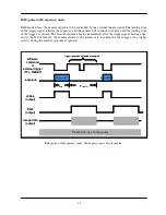
Bulb (pulse-width exposure) mode 

The  term  “bulb”  mode  is  borrowed  from  photography,  denoting  a  camera  setting  in 
which the shutter stays open as long as the shutter button is depressed. Bulb mode in the 
DVC-340 is analogous in that the CCD exposes as long as the trigger signal is asserted 
(a  low  logic  level  on  the  external  trigger  or  a  low  command  on  the  CameraLink  CC1 
control  line).  Upon  the  rising  edge  of  the  trigger  signal,  readout  of  the  exposure  is 
initiated.  Maximum  exposure  time  is  indefinite,  although  dark  current  will  set  the 
practical exposure time limit, depending on the operating temperature and the tolerance 
of the application to dark current pattern noise. 
 

Exposure range:


20MHz  or  40MHz  Readout:

  10us  minimum.  Maximum  limited  by  dark  current  and 

particular application. 

5.3.


Binning 

Binning  is  the  process  of  summing  adjacent  lines  and/or  pixels  in  order  to  increase  dynamic 
range,  sensitivity,  or  both. Binning  can  either  be  accomplished  on  the  CCD  itself  by  summing 
the collected charge (on-chip binning) or in software, after A/D conversion. On-chip binning can 
result in slightly lower noise relative to software binning, under certain circumstances. Because 
fewer  lines  are  actually  read  out  when  binning  vertically,  on-chip  binning  in  the  vertical 
direction  can  produce  a  significant  increase  in  frame  rate  with  increasing  binning  ratios. 
However,  because  the  clocking  cannot  be  accelerated  in  the  horizontal  direction,  horizontal 
binning provides no such speed increase. 
 
In  all  modes  of  operation,  the  DVC-340  is  capable  of  arbitrary  on-chip  binning  (2x,  3x,  4x, 
5x…21x,…)  in  the  vertical  direction,  and  2x,  3x,  and  4x  on-chip  binning  in  the  horizontal 
direction. As vertical binning increases, antiblooming control decreases, so the user must control 
image  illumination  more  carefully  while  binning.  However,  blooming  does  not  cause  any 
damage to the camera. 
 
As  binning  factor  increases,  the  CCD  vertical  registers  are  driven  faster.  This  naturally  causes 
more heating of the CCD and driving electronics. Since dark current generation increases with 
CCD die temperature, a noticeable increase in CCD dark current can occur at very high binning 
factors. 

Summary of Contents for DVC-340

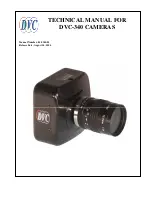
Page 1: ...TECHNICAL MANUAL FOR DVC 340 CAMERAS Manual Number 86 0340 01 Release Date August 24 2006 ...

Page 2: ...ous overlapped exposure mode with electronic shuttering 7 5 2 2 Continuous overlapped extended exposure mode 8 5 2 3 Continuous non overlapped exposure mode 8 5 2 4 Edge triggered exposure single frame capture mode 8 5 2 5 Bulb pulse width exposure mode 9 5 3 BINNING 9 5 4 REGION OF INTEREST 10 6 CCD PHENOMENA 10 6 1 BLOOMING 10 6 2 SMEAR 10 7 MAINTENANCE 11 IMPORTANT WARRANTY INFORMATION 11 7 1 C...

Page 3: ...NNECTORS 23 AUXILIARY CONNECTOR 23 Auxiliary Connector Pin Signal list 23 Pin 1 ENL 23 Pin 2 DIFF_RESET_OUT 23 Pin 3 TTL_RESET 24 Pin 4 GND 24 Pin 5 ENF 24 Pin 6 STROBE and programmable output 24 POWER SUPPLY CONNECTOR PIN ASSIGNMENTS 24 APPENDIX C SPECIFICATIONS 25 ...

Page 4: ... the DVCView imaging application provides full control of up to 8 cameras simultaneously through an intuitive user interface and it enables the user to acquire pan zoom analyze and save imagery and metadata Additionally DVCView provides direct to disk video streaming time lapse capture image averaging image background subtraction and flat fielding For developers DVC also offers a software develope...

Page 5: ...th the DVC 340 camera DVC 340 camera CameraLink or Gigabit Ethernet interface board CameraLink or Gigabit Ethernet cable Regulated power supply Line cord with plug for country of service DVC software CD 3 1 Important information regarding the power supply The DVC 340 power supply can be configured for 115VAC or 220VAC mains voltages via the selection switch on the underside of the unit Before conn...

Page 6: ...e Place DVC Software installation CD in the CD or DVD drive The installer will launch automatically and guide each installation step 4 4 Installing the camera hardware This camera contains sensitive electronic devices that can be damaged by static discharge Use appropriate static control methods when handling the camera Avoid contact with connector pins when cables and plugs are removed Mount the ...

Page 7: ...ignal 5 1 Operating speed The DVC 340 is capable of operating at pixel rates of 20MHz and 40MHz All camera functions e g exposure mode binning ROI etc are operational at either speed subject to the limitations below 5 1 1 20 MHz operation 20MHz operation gives the user the maximum dynamic range and minimum noise floor Dynamic range refers to the maximum signal swing under which the camera meets pe...

Page 8: ...ed via trigger the camera operates continuously in this fashion until it is halted by the host computer Exposure range full resolution no binning or ROI 20MHz Readout Increments of 36 microseconds ranging from 17 3 milliseconds to 2400 seconds 40MHz Readout Increments of 18 microseconds ranging from 8 8 milliseconds to 1200 seconds 5 2 3 Continuous non overlapped exposure mode In this mode the cam...

Page 9: ...nt pattern noise Exposure range 20MHz or 40MHz Readout 10us minimum Maximum limited by dark current and particular application 5 3 Binning Binning is the process of summing adjacent lines and or pixels in order to increase dynamic range sensitivity or both Binning can either be accomplished on the CCD itself by summing the collected charge on chip binning or in software after A D conversion On chi...

Page 10: ...he DVC 340 provides anti blooming control which suppresses blooming under most imaging conditions If signal levels are extreme and such high signal levels cover a large percentage of the field of view blooming may occur The result is jagged vertical bright streaks running below such regions During binning it is possible to bloom in the horizontal direction especially when binning greater than 4x v...

Page 11: ...ing or misuse To ensure optimum image quality with any DVC camera do not remove the protective lens mount cap until ready to mount the camera on the application If the camera is removed from the application immediately replace the cap Doing so will keep dust and other contaminants from accumulating on the optical surfaces In addition please note the following model specific guidelines 7 1 2 Standa...

Page 12: ...arefully unscrew the lens mounting ring and integral filter Place the camera face down on a clean dry surface to prevent particles from accumulating on the CCD faceplate Once the filter is removed Use a CLEAN DRY preferably brand new camel hair lens cleaning brush such as those used by photographers to gently wipe the particles off of the filter Re examine the filter after removing the dust If a s...

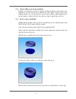
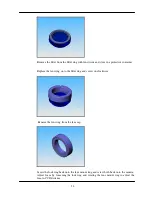
Page 13: ... when not in use 7 1 5 How to remove the IR filter Caution This procedure will cause the focus calibration to be lost Readjustment of the lens back focus will be required after reassembly Loosen the lens mount lock ring with the wrench supplied by DVC Unscrew the lens mount filter assembly ring from the camera body and remove the lock ring from the lens mount ring Hold the lens cap with the pins s...

Page 14: ...eplace the lens ring on to the filter ring and screw on clockwise Remove the lens ring from the lens cap Screw the lock ring back onto the lens mount ring and screw both back onto the camera Adjust focus by loosening the lock ring and rotating the lens mount ring to adjust the lens to CCD distance ...

Page 15: ...erably brand new camel hair lens cleaning brush such as those used by photographers to gently wipe the contaminants off of the CCD Faceplate If in doubt or if the CCD faceplate surface is very dusty please call DVC customer service before proceeding 7 1 6 3 What if the contamination includes a smudge DVC strongly recommends returning the camera to the factory for professional cleaning to avoid dam...

Page 16: ...uipment subjected to misuse accident neglect or improper application Nor does the warranty extend to DVC manufactured equipment that is repaired or altered by anyone other than DVC or those authorized by DVC in writing Products manufactured by other companies but re sold by DVC such as lenses optical and electro optical assemblies power supplies cables image processor boards and software are warra...

Page 17: ...ate and to supply information regarding trademarks used in this publication the absence of a trademark identifier is not a representation that a particular mark is not a trademark All non DVC products brand names company names are trademarks or registered trademarks of their respective owners and appear in this document for reference only Disclaimer The information in this document is provided as ...

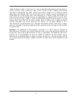
Page 18: ...ly are ignored The camera will remain in this continuous mode until disabled through software command It can then be re armed for another trigger event Continuous overlapped exposure mode with electronic shutter Strobe pulse occurs only if enabled software command or external trigger TTL_RESET Pixel clock runs continuously ENF output exposure image data output strobe output texp trigger ignored un...

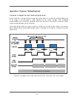
Page 19: ... the camera is operating continuously are ignored The camera will remain in this continuous mode until disabled through software command It can then be re armed for another trigger event Continuous overlapped extended exposure mode Strobe pulse is disabled due to continuous nature of exposure software command or external trigger TTL_RESET Pixel clock runs continuously ENF output exposure image dat...

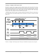
Page 20: ...are ignored The camera will remain in this continuous mode until disabled through software command It can then be re armed for another trigger event Continuous non overlapped exposure mode Strobe pulse occurs only if enabled software command or external trigger TTL_RESET Pixel clock runs continuously ENF output exposure image data output strobe output texp trigger ignored until camera operation ha...

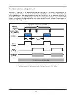
Page 21: ... software Edge triggered exposure mode Strobe pulse occurs only if enabled readout exposure software command or external trigger TTL_RESET Pixel clock runs continuously ENF output exposure image data output strobe output texp Treadout trigger ignored during exposure and readout exposure readout exposure software command or external trigger TTL_RESET Pixel clock runs continuously ENF output exposur...

Page 22: ...ra returns to the armed state awaiting the next trigger Any trigger activity during the readout sequence is ignored Bulb pulse width exposure mode Strobe pulse occurs only if enabled software command or external trigger TTL_RESET Pixel clock runs continuously ENF output exposure image data output strobe output texp trigger ignored until readout complete exposure Treadout exposure software command ...

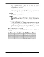
Page 23: ...TL_RESET Input 4 GND 5 ENF Output 6 STROBE INT PULSE Output Pin 1 ENL ENL refers to Enable Line It is an active high TTL signal and is asserted during the valid pixel period on each line as shown in the diagrams in Appendix A It returns low during the inter line period between each line and during the inter frame period between each frame Pin 2 DIFF_RESET_OUT This pin is an active low TTL signal t...

Page 24: ...eturns low between frames Pin 6 STROBE and programmable output STROBE is a TTL output that if enabled is high during the actual sensor exposure time in certain modes Refer to the diagrams in Appendix A for details on STROBE operation with respect to the exposure interval in each mode STROBE is typically used to synchronize an external flash lamp or other device with the camera The STROBE signal ca...

Page 25: ...M Power Connector Camera Link MDR 26 Camera Connector X 20 Standard Tripod mount Camera Mount C mount Lens Mount 18 ozs 505 grams Weight 3 25 H X 3 25 W X 1 73 L Size Mechanical 5 Watts Power 110 220 VAC 50 60 Hz Input Voltage Electrical 20MHz 40MHz 1X1 640x480 55 109 1X2 640x240 109 206 2X2 320x240 109 206 3X3 213x160 160 305 4X4 160x120 205 374 Binning selected examples 12e 20 MHz Read Noise 20 ...

Reviews: