


4
01452 300110
|
1.
Ensure the water tank is clean.
2.
With the power supply off. Open the water supply to the water tank and fill with water until the
ball valve closes and stops further filling. Check the water level is correct and all joints are
sound.
3.
Check the pump has been fully evacuated of all air by removing the bleed screw of the pump
and allow water to escape until no air is present, replace the bleed screw.
4.
Open discharge valve and power the product, the pump should then start to run and push all
air out of the discharge system, when free of air close the discharge valve and the flow will
stop and the pump will switch off after approximately 10 seconds.
Operation
When a draw off point connected to the system is opened the pressure will start to fall and the pump will start
to pressurise the system. The pump will continue to run until demand ceases completely and flow has stopped
(< 3l/m) the pump will run for approximately 10 seconds and will then shutdown.
The pressure will now be sitting at the pump closed valve head value.
Lack of water
If the
pump controller
senses a lack of water the pump will be stopped automatically after approximately 10
seconds and the red failure light will be illuminated.
If the water supply comes back online and a discharge is open the
pump controller
will automatically reset and
start the pump.
If the water supply has been reinstated and the pump has not started automatically the reset button can be
operated which will cause the pump to run for approximately 10 seconds and prime the system, if successful the
pump will then operate normally.
Maintenance
Routine check (6 monthly intervals)
1. Check the pump produces the correct pressure.
2. Check that the pump operates without undue noise or vibration.
3. Check the break tank is clean and that the correct water level has been maintained.
4. Check that all screws are tight on electrical components.
5. Check that the earth connections are tight and making good contact.
Pump removal
Isolate power supply feeding pump set.
Isolate water inlet feeding pump set.
Open an outlet to release system pressure
Isolate the valve located on each flexible connector and remove the flexible from the pump suction and
discharge ports, the pump can now be un-bolted from the base and pulled forward.
The electrical cable can now be removed from the pump terminal box.
The new pump can now be fitted reversing the above procedure.
The
b
reak tank is constructed to have a weir slot as required by the water bylaws to prevent back flow contamination, if
the inlet ball valve or NRV suffered a catastrophic failure the overflow may not be able to keep up with the inflow in
which case excess water will be ejected through the weir slot and onto the plant room floor, if this is not acceptable then
consideration should be given to fitting the
w
ash down set onto a tray with overflow to a drain.
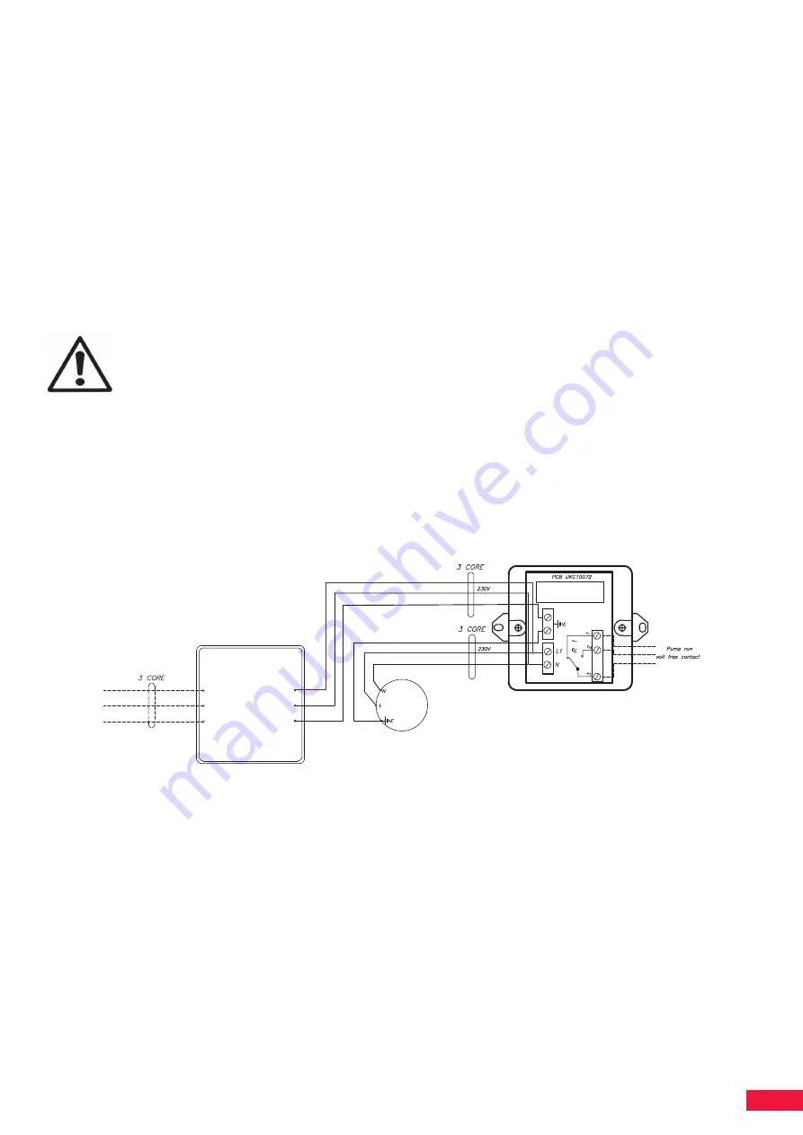
Volt Free Contacts – Pump Running
Both open and closed volt free contacts are available which indicate if the pump is running. See appropriate
drawing for volt free contact wiring configurations. Rating 1A 50v maximum.
Commissioning
[email protected] | 01452 300110
3
REVISION
No.
DATE
NOTES
Mains water supply 15mm
O
ve
rflo
w
/W
arn
in
g
22
m
m
System
connection
15mm push fit
Clearance required for access
Front 500mm
Sides 200mm
Top 500mm
Wall mounting
fixing holes
4 x M8 fixing bolts
482
Access to Cold water break tank
under top cover
338
NOTE
.
Installation of this product should not be carried
out until the installation and operating instruction
have been read and fully understood.
Installation Notes.
1. This product should be installed in a dry frost free environment.
2. It is recommended that the system should be cleaned to BS5449 part 1 1990 before connection
3. Isolating valves must be fitted to all connecting pipework to aid servicing
4. The system pipework should be sized to pass the required flow rate without excessive frictional loss
5. Electrical connections should be carried out by a qualified electrical engineer in accordance with
local site regulations and the latest issue of the IEE regulations.
6. Cold water supply minimum operating pressure at ball valve 0.3 bar. lower pressures will require
a low pressure seat to be fitted to the ball valve.
7. The 22mm overflow pipe should be extended to a position where an overflow will be noticed and rectified.
1 metre of
3 core 1mm2 cable
Electrical connections
Supply
230v single phase + Earth
Connect to a suitable thermal switch or fused supply
A high sensitivity differential switch is also recommended (0.03A)
Pump controller
L
N
E
L
N
E
M
Pump motor
U
V
E
Volt free contact
box
Terminals 1 & 2 close for pump run
Terminals 1 & 3 open for pump run
Relay
Gland for wiring
to volt free contact
642
270
532
420
225
Weir at
opposite end


