background image

Working basis

20

Service Instructions 969 - 06.0 - 03/2019

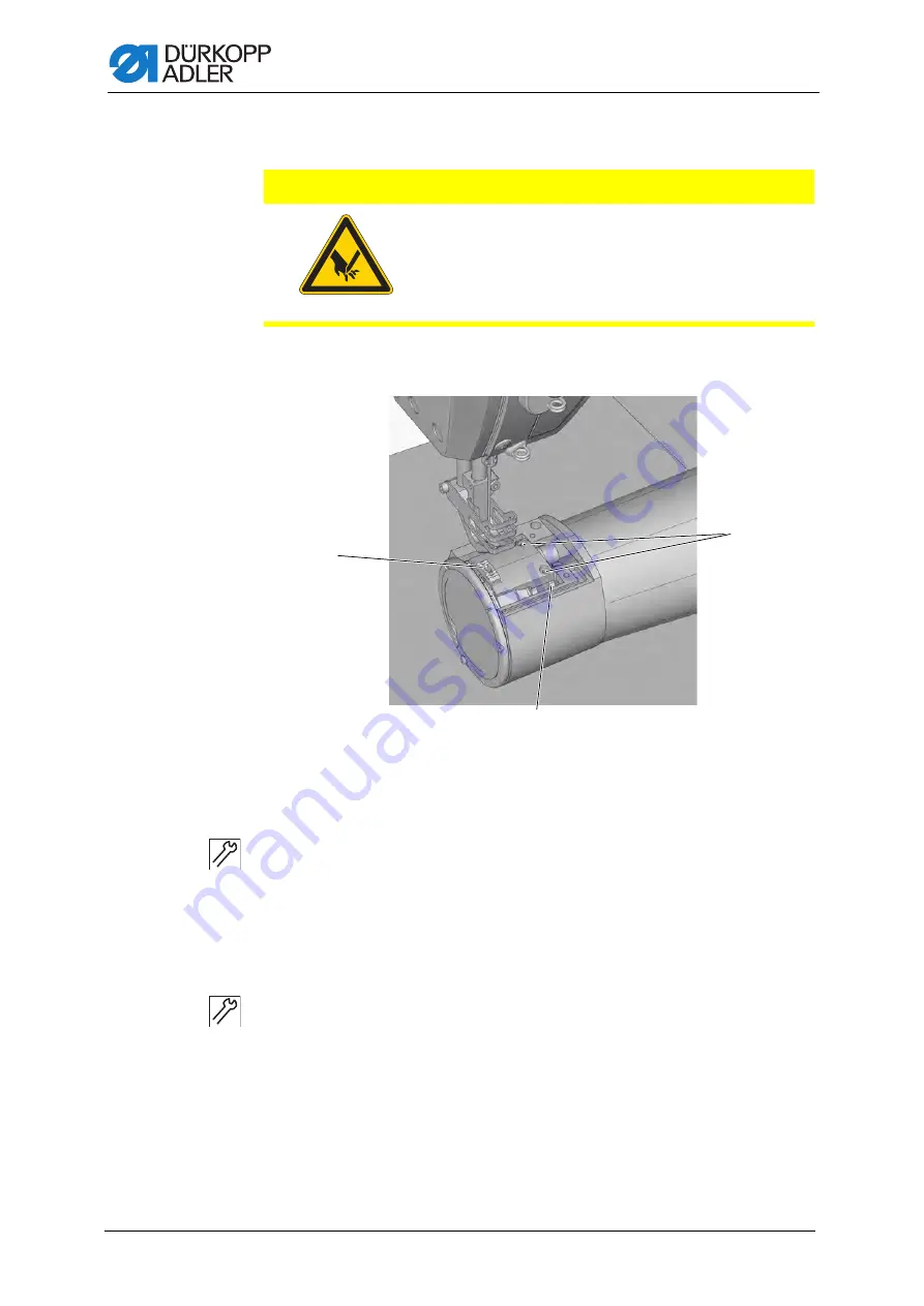
3.3.8 Disassembling and assembling the feed dog

Fig. 8: Disassembling and assembling the feed dog

Disassembling the feed dog

To disassemble the feed dog:

1. Disassemble the throat plate (

p. 19

).

2. Loosen the screws (3).
3. Remove the feed dog (1) from the feed dog carrier (2).

Assembling the feed dog

To assemble the feed dog:

1. Insert the feed dog (1)
2. Slightly tighten the screws (3).
3. Assemble the throat plate.
4. Set the feed dog (1) so that it has an equal amount of play on both 

sides when inside the throat plate.

5. Tighten the screws (3).

CAUTION

Risk of injury from sharp and moving parts!

Puncture or crushing possible.

Switch off the machine before disassembling 
the feed dog.

(1)

- Feed dog

(2)

- Feed dog carrier

(3)

- Screws

Summary of Contents for 969 Classic

Page 1: ...969 Service Instructions...

Page 2: ...er AG and protected by copyright Any reuse of these contents including extracts is prohibited without the prior written approval of D rkopp Adler AG Copyright D rkopp Adler AG 2019 IMPORTANT READ CARE...

Page 3: ...22 3 6 Locking the machine in place 22 3 7 Setting the handwheel into position 24 4 Positioning the arm shaft 25 5 Setting the handwheel scale 26 6 Setting the drive 27 6 1 Setting the drive ratio Cl...

Page 4: ...1 1 Setting the zero stroke of the sewing feet and the tension force of the torsion spring 61 11 1 2 Setting the drive dog of the presser foot bar 63 11 1 3 Setting the feed stroke of presser foot an...

Page 5: ...cating the needle bar 99 16 5 Securing the shafts of the stitch length adjusting wheels 100 16 6 Parts list 102 17 Decommissioning 103 18 Disposal 105 19 Troubleshooting 107 19 1 Customer Service 107...

Page 6: ...Table of Contents 4 Service Instructions 969 06 0 03 2019...

Page 7: ...tended These instructions are intended for Specialists This group has the appropriate technical training for performing maintenance or repairing malfunctions With regard to minimum qualification and o...

Page 8: ...control panel Important Special attention must be paid to this point when performing a step Information Additional information e g on alternative operating options Order Specifies the work to be perf...

Page 9: ...rds and regulations D rkopp Adler cannot be held liable for any damage resulting from Breakage and damage during transport Failure to observe these instructions Improper use Unauthorized modifications...

Page 10: ...About these instructions 8 Service Instructions 969 06 0 03 2019...

Page 11: ...impair safety and damage the machine Only use original parts from the manufacturer Transport Use a lifting carriage or forklift to transport the machine Raise the machine max 20 mm and secure it to pr...

Page 12: ...in warnings Warnings in the text are distinguished by color bars The color scheme is based on the severity of the danger Signal words indicate the severity of the danger Signal words Signal words and...

Page 13: ...atal injury if ignored This is what a warning looks like for a hazard that could result in moderate or minor injury if the warning is ignored Puncture Crushing Environmental damage Symbol Type of dang...

Page 14: ...ironmental damage if ignored This is what a warning looks like for a hazard that could result in property damage if ignored CAUTION Type and source of danger Consequences of non compliance Measures fo...

Page 15: ...cables To lay the cables 1 Lay any excess cabling neatly in proper cable snakes 2 Bind together the cable loops with cable ties Tie loops wherever possible to fixed parts Important The cables must be...

Page 16: ...to remove the individual covers The covers need to be refitted in reverse order Re installation will therefore not be described unless special requirements have to be followed 3 3 1 Access to the und...

Page 17: ...d 1 completely 3 3 2 Removing the arm cover If necessary each of the two covers can be removed separately Fig 2 Removing the arm cover Removing the left arm cover To remove the left arm cover 1 Turn l...

Page 18: ...the right arm cover 4 2 Raise the right arm cover 4 and disconnect the power plug for the fan that is attached to the underside of the cover 3 Lift the right arm cover 4 up and off 3 3 3 Removing the...

Page 19: ...ate Fig 4 Removing the cover plate To remove the cover plate 1 Loosen the screws 2 2 Remove the cover plate 1 3 3 5 Removing the belt cover Fig 5 Removing the belt cover To remove the belt cover 1 Loo...

Page 20: ...d tension plate Fig 6 Removing the thread tension plate To remove the thread tension plate 1 Remove the right arm cover 3 p 15 Important The thread tension plate is connected to cables and hoses that...

Page 21: ...sembling the throat plate To disassemble the throat plate 1 Swivel up the sewing foot 2 Loosen the screws 1 3 Remove the throat plate 2 CAUTION Risk of injury from sharp and moving parts Puncture or c...

Page 22: ...feed dog 1 from the feed dog carrier 2 Assembling the feed dog To assemble the feed dog 1 Insert the feed dog 1 2 Slightly tighten the screws 3 3 Assemble the throat plate 4 Set the feed dog 1 so tha...

Page 23: ...rews These flats increase the stability of the connection and allow the component to be assembled to the shaft at an angle Important Always ensure that the screw faces are completely flush with the su...

Page 24: ...f these shafts is as small as possible or 0 3 6 Locking the machine in place Some settings allow for the sewing machine to be locked in place at the setting position To do this the locking peg from th...

Page 25: ...Turn the handwheel until the appropriate slot 1 is in front of the locking opening 3 Smaller slot at handwheel position 180 Larger slot at handwheel position 206 2 Insert the locking peg 2 with the a...

Page 26: ...o position Some settings require that the specified handwheel position be set using the angle scale Fig 12 Setting the handwheel into position To set the handwheel into position 1 Turn the handwheel u...

Page 27: ...machine casting Cover left arm cover p 15 Fig 13 Positioning the arm shaft To position the arm shaft 1 Loosen the threaded pins 1 on the arm shaft crank 2 Turn the arm shaft crank so that the threaded...

Page 28: ...e V ribbed belt p 27 2 Loosen the screws 1 3 Assemble belt cover and handwheel 4 Lock the machine in place at position 2 p 22 5 Move the handwheel into the 180 position 6 Slide a hexagonal wrench thro...

Page 29: ...ve belts must be disassembled and the pulley changed to the opposite position The drive belt is then refitted and tensioned Cover Belt cover p 17 6 1 1 Disassembling the V ribbed belt Fig 15 Disassemb...

Page 30: ...ween the faces of the two pulleys Fig 16 Setting the drive pulley To set the drive pulley 1 Loosen the screws 3 2 Pull the drive pulley 2 off the motor shaft and put it back on the other way round 3 S...

Page 31: ...Setting the belt tension To set the belt tension 1 Insert the V ribbed belt 7 2 Turn the tensioning roller 6 with the belt tensioner 3 against the V ribbed belt 7 3 Insert a hexagonal wrench into the...

Page 32: ...ped with a 1 step pulley Cover Belt cover p 17 6 2 1 Disassembling the V ribbed belt Fig 18 Disassembling the V ribbed belt To disassemble the V ribbed belt 1 Loosen the screws 4 2 Rotate the tensioni...

Page 33: ...lleys are in alignment Fig 19 Setting the drive pulley To set the drive pulley 1 Loosen the screws 3 2 Pull the drive pulley 2 off the motor shaft and put it back on the other way round 3 The drive pu...

Page 34: ...Setting the belt tension To set the belt tension 1 Insert the V ribbed belt 7 2 Turn the tensioning roller 6 with the belt tensioner 3 against the V ribbed belt 7 3 Insert a hexagonal wrench into the...

Page 35: ...otor and main shaft must be entered correctly into the control program of the machine 6 3 1 Importing the drive ratio into the control program Fig 21 Importing the drive ratio into the control program...

Page 36: ...set the reference position of the handwheel 1 Select parameter setting mode on the OP1000 control panel 1 and set the parameter t 08 10 Instructions for use DAC basic classic 2 Manually rotate the han...

Page 37: ...adjusting wheel than on the upper adjusting wheel It is not possible to set a larger stitch length on the upper adjusting wheel than on the lower adjusting wheel CAUTION Risk of injury from moving pa...

Page 38: ...he maximum stitch length that can be achieved with the built in sewing equipment Fig 24 Setting the upper stitch length adjusting wheel To set the upper stitch length adjusting wheel 1 Switch on the m...

Page 39: ...the seam correspond with the set stitch lengths The lower stitch length adjusting wheel can only be turned up to the stitch length set on the upper stitch length adjusting wheel Fig 25 Setting the low...

Page 40: ...n be placed on the maximum stitch length that can be set 12 9 or 6 mm can be selected as the maximum stitch length The appro priate throat plate must be selected for the selected maximum stitch length...

Page 41: ...ert a sheet of paper Sew a seam forward stop slightly shift the sheet sideways and sew a seam backward The punctures of the forward and backward stitches have to lie exactly next to one another Cover...

Page 42: ...ow refer to both Classic machines and machines equipped with the option Heavy Transport Order First check the following setting Needle bar linkage p 48 8 1 Setting the feed dog position Proper setting...

Page 43: ...t and can be moved on this shaft Cover Tilt the machine head p 14 Fig 28 Moving the feed dog carrier in sewing direction To move the feed dog carrier in sewing direction 1 Set the upper stitch length...

Page 44: ...enter 6 Tighten the screw 4 Important When doing this make sure that the sliding shaft 7 is held firmly in place by the clamp 8 and the adjusting ring 9 7 Press theadjusting ring 5 against the casting...

Page 45: ...o the 190 position and the upper stitch length adjust ing wheel to the maximum stitch length When the stitch regulator is pressed down the feed dog stops Cover right arm cover p 15 Fig 30 Setting the...

Page 46: ...ne head p 14 Fig 31 Setting the feed dog height at top dead center To set the feed dog height at top dead center 1 Position the feed dog 1 at top dead center 2 Loosen the screw 3 3 Push up the feed do...

Page 47: ...eel position 270 At 90 the feed dog is in the upward movement at 270 in the downward movement Cover right arm cover p 15 Fig 32 Setting the feed dog stroke movement To set the feed dog stroke movement...

Page 48: ...g value Stroke eccentric sewing feet 1 23 Stroke eccentric feed dog 5 5 Pusher eccentric feed dog 6 230 Cover left and right arm cover p 15 Fig 33 Setting the feeding eccentric with adjusting tube CAU...

Page 49: ...e pusher eccentric of the feed dog 6 1 Loosen the threaded pins on the pusher eccentric 6 2 Insert the adjusting tube 3 into the first hole in the direction of rotation 4 3 Press the adjusting tube 3...

Page 50: ...e setting begins p 22 9 1 Moving the needle bar linkage sideways Proper setting When the stitch length is set to 0 and the value set on the handwheel scale is 90 needle bar the sewing foot bar and the...

Page 51: ...0 2 Move the handwheel into the 90 position 3 Loosen the screw 1 4 Loosen the screws 2 5 Loosen the screws 3 6 Loosen the screw 8 7 Move the needle bar linkage 7 sideways so that needle bar 4 feeding...

Page 52: ...llel to the presser foot bar Cover left and right arm cover p 15 Fig 35 Aligning the needle bar linkage in the sewing direction To align the needle bar linkage in the sewing direction 1 Loosen the scr...

Page 53: ...setting When you press down on the toothed belt approximately in the center between the pulleys with a force of 10 N in the direction of the arrow the belt should deflect about 3 mm Cover Belt cover p...

Page 54: ...of the toothed belt 2 4 Check and if necessary adjust the toothed belt tension 10 2 Setting the dead center of the reciprocating hook movement Proper setting Fig 37 Setting the dead center of the reci...

Page 55: ...to the lower dead center 2 Loosen screws 1 and 2 Fig 39 Setting the dead center of the reciprocating hook movement 3 3 Set the driver sideways The driver nose 5 points exactly to the marking 4 4 Tight...

Page 56: ...set to 0 and the machine is locked in place at position 1 the hook tip is at the center in relation to the needle axis Cover right arm cover p 15 Fig 40 Setting the loop stroke position 1 To set the l...

Page 57: ...lower third of the needle groove 3 6 Tighten the screws 2 7 Remove the lock 8 Tighten the screws 1 10 4 Setting the hook clearance Proper setting Lock the machine in place at position 1 The maximum di...

Page 58: ...n the needle 2 at top dead center 4 Loosen the screws 6 of the cover ring 5 5 Remove the cover ring 5 6 Remove the hook 7 Loosen and remove the loop support 8 Loosen the screw for the hook cage 1 9 Re...

Page 59: ...s the needle lightly preventing the needle from colliding with the hook when pressure is exerted on the needle Fig 43 Setting the needle guard To set the needle guard 1 Move the machine to loop stroke...

Page 60: ...been engraved on the distance piece There is a matching distance piece for every needle thickness which must be inserted accordingly Cover Tilt the machine head p 14 Fig 44 Setting the loop former To...

Page 61: ...needle has to be inserted Operating Instructions Proper setting The machine is locked in place at position 1 and the upper stitch length adjusting wheel is set to 0 The hook tip is level with the low...

Page 62: ...ok tip 3 is in the middle of the lower third of the groove 4 for the needle Important Do not twist the needle to the side The groove 4 must face toward the hook 5 Tighten the screw 1 6 Remove the lock...

Page 63: ...f the sewing feet and the tension force of the torsion spring Proper setting The connecting rods are in a line The ball pin is touching the stop screw The torsion spring is twisted 15 20 Cover left an...

Page 64: ...Loosen the screw in the slot 5 2 Loosen the counternut 8 3 Rotate the frame 2 so that the clips 1 are in a line 4 Turn the stop screw 9 so that the ball pin 7 is in contact with it and the clips 1 re...

Page 65: ...me height The drive dog is assembled to the presser foot bar in such a position that the needle shaft touches the presser foot bar Cover left and right arm cover p 15 Head cover p 16 Fig 47 Setting th...

Page 66: ...s onto the plate 7 10 Tighten the drive dog screw 14 11 Assemble the assembly 6 Ensure there is an axial play of 0 2 0 3 mm between the sliding block 12 and the floor of the gully 5 11 1 3 Setting the...

Page 67: ...foot 1 Move the handwheel into the 0 position 2 Set the stitch length to 0 3 Set the zero stroke of the feet p 61 4 Loosen the screw 5 5 Place the plate 3 under the feet so that the feeding foot 4 is...

Page 68: ...5 Cover left and right arm cover p 15 Fig 49 Setting the stroke movement for the feeding foot To set the stroke movement for the feeding foot 1 Screw in the threaded pin 7 so that there is a stroke 2...

Page 69: ...teed clearance of 0 3 0 5 mm between the stroke lever and the drive dog Cover Head cover p 16 Fig 50 Setting the foot stroke using the hand lever To set the foot stroke using the hand lever 1 Move the...

Page 70: ...e using the pneumatic cylinder To set the foot stroke using the pneumatic cylinder 1 Move the handwheel into the 0 position The presser foot rests on the throat plate 2 Loosen the counternut 2 3 Activ...

Page 71: ...thin or very thick the setting of the spring travel must be adjusted accordingly thin material normal spring travel initial position horizontal thick material long spring travel initial position vert...

Page 72: ...nder levers are approximately parallel to one another The winder is switched off mechanically when the winder pulley reaches a distance of L 8 mm from the internal diameter of the bobbin The roller is...

Page 73: ...hed off 9 Loosen the screw 6 10 Set the blocking lever 11 to the base of the slot in the blocking cam 10 11 Set the axial play of the blocking cam 10 to approx 0 5 mm 12 Keep the blocking cam 10 in th...

Page 74: ...centric 5 so that there is a gap of 0 5 mm between the friction disk 8 and the rubber pulley 9 4 Tighten the screw 6 Fig 56 Setting the winder 4 5 Loosen the screws 12 6 Set the position of the micros...

Page 75: ...lever 9 engages in the slot in the blocking cam 10 At this position the microswitch 11 must switch the motor off If the microswitch 11 fails to switch off the motor correct the position of the microsw...

Page 76: ...guide must be changed Cover right arm cover p 15 Fig 57 Setting the hook thread guide To set the hook thread guide 1 Insert and wind on the hook thread If the hook thread is concentrated at one end o...

Page 77: ...ged in the setting groove of the control cam the handwheel scale indicates 120 Cover right arm cover p 15 Fig 58 Setting the thread cutter timing To set the thread cutter timing 1 Loosen the screw 1 2...

Page 78: ...g groove 7 9 Tighten the screws 4 13 2 Setting the initial position of the thread cutter and the position of the thread pulling knife Proper setting When the lever is moved up against the pin the gap...

Page 79: ...nd the position of the thread pulling knife 1 To set the initial position of the thread cutter and the position of the thread pulling knife 1 Move the handwheel into the 80 position 2 Loosen the screw...

Page 80: ...ing the initial position of the thread cutter and the position of the thread pulling knife 2 4 Set the thread pulling knife 5 such that the marking 6 lines up with the blade of the fixed knife 7 5 Ext...

Page 81: ...to the right against feeler gage and feed dog mounting plate 10 8 Push the lever 2 to the left 9 Place a feeler gage 0 1 mm between roll 12 and cutoff curve 11 at handwheel position 80 10 Push the ro...

Page 82: ...dle thread 14 preventing it from being cut Important The needle thread 14 must be positioned in the slot 13 of the thread pulling knife 5 15 If necessary adjust the position of the thread pulling knif...

Page 83: ...To set the pneumatic cylinder lever 1 Turn the lever 6 such that it rests against the pin 5 2 Loosen the screw for the lever 2 through the assembly opening 1 3 Turn the lever 2 until the piston 3 mak...

Page 84: ...the thread to be cut in a reliable manner Disturbance Very rapid wear of the knife if the pressure is set too high Fig 64 Setting the cutting pressure To set the cutting pressure 1 Turn the screw 1 In...

Page 85: ...65 Setting the hook thread clamp To set the hook thread clamp 1 Complete a few short seams including thread cutting at the seam end 2 Measure the length of the hook thread end 1 at the start of the s...

Page 86: ...system allows the machine to start at low speed and build up to maximum speed over a defined number of stitches Fig 66 Soft start To activate soft start 1 Activate the soft start setting on the OP100...

Page 87: ...nformation This chapter describes the machine specific functions of the OP1000 control panel Refer to the Instructions for use DAC basic classic for further information on the control and the OP1000 c...

Page 88: ...after sewing stops Needle up down Sewing foot lift after thread cutter Activates or deactivates the sewing foot lift after the thread cutter Sewing foot lift after sewing stop Activates or deactivate...

Page 89: ...eter Selects subprogram D Increases parameter Selects subprogram OK Calls parameters or saves them Confirms parameters P Starts or ends the parameter mode A Decreases parameter Changes user level Sele...

Page 90: ...03 2019 D Decreases parameter Selects subprogram Reset Resets the piece counter Seam program button group Seam program I Activates seam program I Seam program II Activates seam program II Seam progra...

Page 91: ...s for repeated use It is possible to create seam programs consisting of 4 or 6 seam sections and up to 25 freely programmable seam sections The following parameters can be set for each individual seam...

Page 92: ...Programming 90 Service Instructions 969 06 0 03 2019...

Page 93: ...sk of injury from sharp parts Punctures and cutting possible Prior to any maintenance work switch off the machine or set the machine to threading mode WARNING Risk of injury from moving parts Crushing...

Page 94: ...he compressed air gun so that the particles do not fly close to people Make sure no particles fly into the oil pan NOTICE Property damage from soiling Lint and thread remnants can impair the operation...

Page 95: ...Area around the needle 1 Feed dog 2 Thread pulling knife 3 Hook and thread cutter 4 To clean the machine 1 Switch off the machine 2 Disassemble the throat plate p 19 3 Remove any lint and thread remna...

Page 96: ...injury from contact with oil Oil can cause a rash if it comes into contact with skin Avoid skin contact with oil If oil has come into contact with your skin wash the affected areas thoroughly NOTICE...

Page 97: ...l marking 3 Information In the Classic equipment version of the machine the oil level indicator will light up red if the oil level has dropped below the minimum level marking To top off the oil 1 Swit...

Page 98: ...ig 70 Setting the operating pressure To set the operating pressure 1 Pull the pressure controller 1 up 2 Turn the pressure controller until the pressure gage 2 indicates the proper setting Increase pr...

Page 99: ...a daily basis Fig 71 Draining the water condensation To drain water condensation 1 Disconnect the machine from the compressed air supply 2 Place the collection tray under the drain screw 3 3 Loosen th...

Page 100: ...n the filter element 1 5 Blow out the filter element 1 using the compressed air gun 6 Wash out the filter tray using benzine 7 Tighten the filter element 1 8 Tighten the water separator 2 9 Tighten th...

Page 101: ...foot 3 Place the grease gun onto the lubricating nipple 1 on the needle bar frame and keep pressing until the flow of grease stops The lubricating nipple 1 is used to lubricate the upper part of the n...

Page 102: ...ting wheels need to be secured Fig 74 Securing the shafts of the stitch length adjusting wheels 1 To secure the shafts of the stitch length adjusting wheels 1 Remove the ventilation grid p 17 2 Loosen...

Page 103: ...e screws 6 Remove the upper stitch length adjusting wheel 1 Tighten the screw 10 Only tighten the screw 10 far enough to secure the shaft making sure that the shaft cannot move easily but the stitch l...

Page 104: ...gth can still be set The shaft of the lower stitch length adjusting wheel has been secured Place the lower stitch length adjusting wheel 3 Tighten the screws 8 7 Align the lever 7 such that it is seat...

Page 105: ...m soiling 6 Cover the control to protect it from soiling 7 Cover the entire machine if possible to protect it from contamination and damage WARNING Risk of injury from a lack of care Serious injuries...

Page 106: ...Decommissioning 104 Service Instructions 969 06 0 03 2019...

Page 107: ...e national regulations When disposing of the machine be aware that it consists of a range of different materials steel plastic electronic components etc Follow the national regulations when disposing...

Page 108: ...Disposal 106 Service Instructions 969 06 0 03 2019...

Page 109: ...if an error occurs that is not described here Do not attempt to correct the error yourself Code Possible cause Remedial action 1000 Sewing motor encoder plug Sub D 9 pin not connected Connect encoder...

Page 110: ...r Replace encoder 1010 External synchronizer plug Sub D 9 pin not connected Connect cable of external synchronizer to control use correct connection Sync Only required for machines with transmission 1...

Page 111: ...LEDs of DACextension box Performing a software update 2121 DA stepper card 1 encoder plug Sub D 9 pin not connected Connect encoder cable to the control use correct connection 2122 DA stepper card 1 f...

Page 112: ...circuit Disconnect 37 pin plug if error persists replace control Test inputs outputs for 24 V short circuit 3106 U24 V I2 T overload One or several magnets defective 3107 Pedal not connected Connect...

Page 113: ...6363 No valid data on internal and external EEprom software version is not compatible with the internal data storage device emergency operating features only Check machine ID connection Switch off th...

Page 114: ...sion box 7801 Software version error DAC classic only only the functions of the DAC basic will remain available Performing a software update Replace control 7802 Software update error DAC classic only...

Page 115: ...d tensions Thread guiding parts such as thread tube thread guide or thread take up disk are sharp edged Check threading path Throat plate hook or spread have been damaged by the needle Have parts rewo...

Page 116: ...material the sewing material thickness or the thread used Check thread tensions Needle thread and hook thread have not been threaded correctly Check threading path Needle breakage Needle thickness is...

Page 117: ...dle system 794 7x23 328 1000H Needle strength Nm 140 280 200 330 140 280 200 330 140 280 Needle thread thickness Nm 40 3 5 3 40 3 5 3 braided thread 1 6 40 3 5 3 40 3 5 3 braided thread 1 6 40 3 5 3 H...

Page 118: ...forward or back by drive motor power Initial alignment stitch by pressing the electronic handwheel Automatic wick lubrication with an inspection glass housed in the arm for lubricating the machine and...

Page 119: ...Appendix Service Instructions 969 06 0 03 2019 117 21 Appendix Fig 76 Wiring diagram...

Page 120: ...Appendix 118 Service Instructions 969 06 0 03 2019...

Page 121: ......

Page 122: ...d GERMANY Phone 49 0 521 925 00 E mail service duerkopp adler com www duerkopp adler com Subject to design changes Part of the machines shown with additional equipment Printed in Germany D rkopp Adler...
Reviews: