DuraVision FDV1001T User Manual Download Page 18

17

Chapter 3  Settings and Adjustments

Tab

Setting /  

adjustable item

Setting / 

adjustable value PC Video

Setting / adjustable content
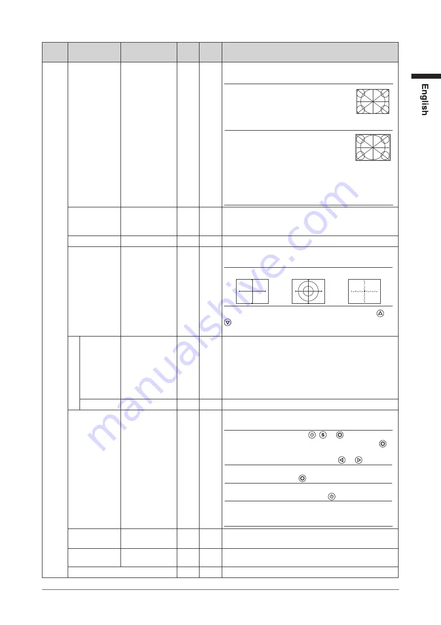
Others Video Aspect

Normal/100%

√ 

Configures the display range of the input image 
(overscan).

Normal

: Displays the input image 

with the outmost parts 
slightly cut off.
* This is how display devices 

normally display images.

100%

: Displays most of the input 

image.
* Because a part of the 

image which normally 

gets cut off is displayed as 

well, noise may be visible 

around the outmost parts, 

depending on the input 

signal.

Power Save

Disable/Enable

√ 

√ 

Automatically turns off the power supply if no video signal 
has been received for 15 minutes during PC or video 
viewing.

Reverse

Off/On

√ 

√ 

Displays the image upside down (180 degree rotation).

Crosshair

Off/Fine/Circle/ 
Broken Line

√ 

√ 

Displays a crosshair as a reference for the position of the 

image.

“Fine”

“Circle”

“Broken Line”

(When the settings menu is not displayed, pressing   or 

 switches between displaying and not displaying the 

crosshair.)

Color

When “Fine” is 

selected:

Black/White/Red/

Green

When “Circle” or 

“Broken Line” is 

selected:

Black/White

√ 

√ 

Configures the color of the crosshair.

Width

Narrow/Wide

√ 

√ 

Configures the thickness of the crosshair’s lines.

Beep

Off/On

√ 

√ 

Sets button press sounds and connection error sounds to 
on or off.

•  Short beep

: - When  ,   or   is pressed.

- When an item is selected with  .

- When a maximum or minimum 

value is set with   or  .

•  Long beep

: When registration is performed 

with  .

•  2 short beeps : When the Setting menu is 

displayed and   is pressed.

•  4 short beeps : - When there is no input signal.

- When a frequency out of the 

specified range is received.

Language

日本語

/English

√ 

√ 

Configures the displayed Setting menu and message 
language.

Touch Panel

PC+VIDEO/PC/

VIDEO

√ 

√ 

Select an input that enables touch panel operation.

Information

√ 

√ 

Reviews the input signals, usage time and model name.

Summary of Contents for FDV1001T

Page 1: ...Important Please read this User s Manual carefully to familiarize yourself with safe and effective usage Please retain this manual for future reference...

Page 2: ......

Page 3: ...rporation PC 9801 and PC 9821 are trademarks of NEC Corporation EIZO the EIZO Logo ColorEdge DuraVision FlexScan FORIS RadiCS RadiForce RadiNET Raptor and ScreenManager are registered trademarks of EI...

Page 4: ...ot open the cabinet or modify the unit Opening the cabinet or modifying the unit may result in fire electric shock or burn Refer all servicing to qualified service personnel Do not attempt to service...

Page 5: ...e and result in fire or electric shock Use the correct voltage The unit is designed for use with a specific voltage only Connection to another voltage than specified in this User s Manual may cause fi...

Page 6: ...the AC adapter Do not place the AC adapter on top of things that trap heat Keep the AC adapter away from heat sources and direct sunlight Not doing so may result in fire Do not touch with bare hands...

Page 7: ...oking new and to prolong its operation lifetime Refer to Cleaning on the next page The LCD panel is manufactured using high precision technology Although missing pixels or lit pixels may appear on the...

Page 8: ...e clearance between the panel and the panel frame NOTE The optional ScreenCleaner is recommended for cleaning the panel surface If necessary the stains on the panel surface can be removed by moistenin...

Page 9: ...oduction 9 1 1 Features 9 1 2 Package Contents 10 Chapter 2 Assembly 11 Chapter 3 Settings and Adjustments 14 3 1 Buttons 14 3 2 Basic Operation and Functions 15 Chapter 4 Troubleshooting 18 Chapter 5...

Page 10: ...LCD panels No mercury a hazardous substance is used Analog signal support PC signal D Sub mini 15 pin connector 1 FDX1001T FDX1201T Horizontal scanning frequency 24 kHz 50 kHz Vertical scanning frequ...

Page 11: ...nitor AC Adapter Cable Tie Handle 2 pcs Handle mounting screw M5 10 mm 4 pcs User s Manual Limited Warranty included EIZO LCD Utility Disk CD ROM 1 RS 232C Cable 1 The disk includes the touch panel dr...

Page 12: ...3 410 16 1 213 8 4 125 4 9 48 1 89 57 2 0 5 2 25 0 02 88 9 0 5 3 5 0 02 146 1 0 5 5 8 0 02 220 1 8 7 0 04 37 1 46 160 6 3 23 0 91 6 4 0 25 Handle mounting holes 6 12 0 24 0 47 Rack mounting holes Vid...

Page 13: ...02 190 5 0 5 7 5 0 02 265 1 10 4 0 04 37 5 1 48 430 16 9 272 10 7 22 0 87 47 1 85 26 1 02 26 1 02 146 5 7 88 3 46 6 4 0 25 Handle mounting holes 6 12 0 24 0 47 Rack mounting holes Video input connect...

Page 14: ...y Electric Industries Association EIA 1 Attach the two handles from the front and secure them from the rear using handle mounting screws M5 10 mm 4 pcs Handle 2 Attach the monitor to the rack while ho...

Page 15: ...each menu and saves the setting or adjustment results 3 button Used to select the setting or adjustment items or to increase or decrease the adjustment values on each menu When the settings menu is no...

Page 16: ...tments 3 2 Basic Operation and Functions Basic operation of Setting menu 1 Displaying Setting Menu Press 2 Setting Adjusting 3 Exiting Choose Exit with or and press NOTE Keeping pressed for 2 seconds...

Page 17: ...1 Clock Adjust this when vertical bars appear Phase Adjust this when the screen appears to flicker or blur Position Adjust this when the display positioning is misaligned Range Adjustment Provides au...

Page 18: ...a reference for the position of the image Fine Circle Broken Line When the settings menu is not displayed pressing or switches between displaying and not displaying the crosshair Color When Fine is s...

Page 19: ...n displaying the same image for extended periods of time please set up the screen saver and or make use of the power saving function When displaying on a PC screen Problems Possible cause and remedy T...

Page 20: ...s settings of the touch panel driver If the check is already applied perform the calibration Other login user may have changed the setting Set the touch panel driver again Restart DMC Touch Panel Conf...

Page 21: ...2B EDID structure 1 3 Touch Panel OS Microsoft Windows 7 Service Pack 1 32 bit 64bit Microsoft Windows Vista Service Pack 2 32 bit Microsoft Windows XP Service Pack 3 32 bit Not compatible with Mac O...

Page 22: ...l Scan Frequency 56 70 5 Hz Non interlace Max Dot Clock 31 MHz Input Signal Connector D Sub mini 15 pin 1 Input Signal Sync Separate TTL positive negative Input Signal Video Analog Positive 0 7Vp p 75...

Page 23: ...76 mm 184 32 mm Resolution 1024 dots 768 lines Max Display Color Approx 16 7 million colors PC input Horizontal Scan Frequency 24 50 kHz Vertical Scan Frequency 55 75 Hz Non interlace Max Dot Clock 6...

Page 24: ...in unit 20 90 R H wet bulb temperature 39 C 102 F no condensation AC adapter 20 85 R H no condensation Storage humidity 10 90 R H wet bulb temperature 39 C 102 F no condensation Pressure Operating 700...

Page 25: ...hase Phase means the sampling timing to convert the analog input signal to a digital signal Phase adjustment is made to adjust the timing It is recommended that phase adjustment be made after the cloc...

Page 26: ...0 VESA 31 50 37 50 75 00 Negative Negative 800 600 VESA 36 00 35 16 56 25 Positive Positive 800 600 VESA 40 00 37 88 60 32 Positive Positive 800 600 VESA 50 00 48 08 72 19 Positive Positive 800 600 VE...

Page 27: ...rioration of expendable parts such as the LCD panel and or backlight etc e g changes in brightness changes in brightness uniformity changes in color changes in color uniformity defects in pixels inclu...

Page 28: ...n Phone 81 76 277 6792 Fax 81 76 277 6793 8 5B Phone 86 512 6252 0100 Fax 86 512 6252 1508 4th Edition November 2012 00N0L625D1 U M FDX1001T R AL Copyright 2010 2012 EIZO NANAO CORPORATION All rights...

Reviews: