DuraComm HE1U Series Manual Download Page 8

Section 4 | Remote Monitoring and Control Setup 
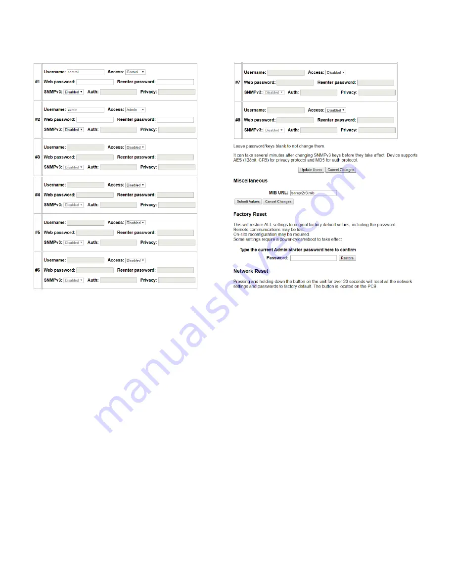
User Setup 


Password changes and hard resets are performed by using this page. Care should be taken when 
changing any of these settings. 
 
NOTE: To hard reset your device back to factory settings, perform a factory reset here, or press the 
red button on the on-board 

remote control unit PCB and hold it for more than 30 seconds (you will 

need to remove the cover on the DuraComm unit, and connect power to the battery terminals). Re-
connect to the unit through your web browser by entering the factory supplied IP address and HTTP 
port (see Network Setup). 


All setup requires an administrative user to log into the DuraComm internet ready unit. Click the 

‘Login’ button in the top menu, and you should see the 

following User Login screen. 

Note: These screenshots are taken from a DuraComm internet-ready MU series and show 
typical setup information for all model numbers in the series (except for the model number).


Figure 5. User setup page. 

Summary of Contents for HE1U Series

Page 1: ...connect 10 0 12 5 VDC Product Dimensions 19 x 14 x 1 75 in 19 Rack Mount 1U Height Shipping Dimensions 21 x 15 x 8 in Shipping Weight 12 lbs intended to be used with external charger to support large...

Page 2: ...Internet 6 Prerequisites 6 Determining the IP Address of the Unit 6 Using DHCP 6 Using Static IP and Network Configuration 6 Open a Web Connection to the Unit 7 Section 4 Remote Monitoring and Contro...

Page 3: ...AC voltage power supply voltage battery voltage power supply current battery current and internal temperature as well as the ability to remotely control the power supply ON OFF state and battery conn...

Page 4: ...Size for Current Capacity Insulated Wire Single Conductor in free air Current Level in Amperes Wire Size Requirements According to MIL W 5088B Up to 5 feet Up to 10 feet 7 AMPERES 20 AWG 18 AWG 14 AM...

Page 5: ...model Rear Connectors 20 84mm 5V G Alarm OUT Alarm IN Factory Jumper Figure 3 Alarm wiring shown with factory jumper to silence alarm condition Between 5V and Alarm IN Output Status Between G and Ala...

Page 6: ...ith a base address of 70 B3 D5 6B 3 Write down the IP address of the unit then proceed to the section in this manual named Open a Web Connection to the Unit Using Static IP and Network Configuration I...

Page 7: ...n the browser see the screenshot below If you are unable to connect to the device with the browser you will need to use a terminal with a USB connection to access the device and configure the IP addre...

Page 8: ...to remove the cover on the DuraComm unit and connect power to the battery terminals Re connect to the unit through your web browser by entering the factory supplied IP address and HTTP port see Networ...

Page 9: ...unit Factory default username and password are as follows Admin users have full user control of the device Username admin Password admin Control users have limited control capability access all scree...

Page 10: ...nder SNMP Traps MIB Browsers and SNMP Monitoring The MIB file for the DuraComm unit can be downloaded after you connect to it with your browser Go to the Device Setup page and log in to the unit Halfw...

Page 11: ...com would send a text message to the Verizon user at phone number 816 555 1234 Here are the most common carrier addresses Alltel phonenumber message alltel com AT T phonenumber txt att net T Mobile p...

Page 12: ...file size reaches 5MB Download all log files before deleting them The ability to log readings when an alarm occurs is included To turn off periodic logging enter 0 as the logging rate You can set up...

Page 13: ...s on the left are left blank the channel will be hidden on the status screen Inputs and outputs of the DuraComm internet ready unit are wired as shown on the Sensor Setup screen The user can enter tex...

Page 14: ...n or control user to adjust the digital outputs The digital outputs can be controlled by the buttons on the status page mobile page or via SNMP on the unit Optionally they can be automatically control...

Page 15: ...ng and Control Status Page This screen shows the status of all analog and digital inputs A user can also download the Log file from this page AC Voltage is approximate A simplified version of the stat...

Page 16: ...re Range 22 to 158 F 30 to 70 C Storage Temperature 40 to 185 F 40 to 85 C Safety Withstand Voltage I P O P 3 KVAC I P FG 2 KVAC O P FG 0 5 KVAC I P O P 3 KVAC I P FG 2 KVAC O P FG 0 5 KVAC I P O P 3...

Page 17: ...uires any product needing in or out of warranty service to be returned to DuraComm All requests for warranty service must be accompanied by proof of purchase such as a bill of sale with purchase date...

Reviews: