

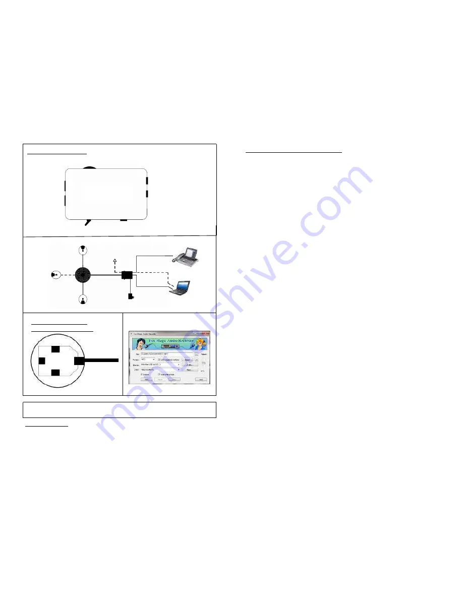
connection diagrams
Volume control Voicebox
to Voicebox
1
2
To Headsetsocket
USB to PC
18 V DC
AC Adapter
ON - OFF
Tele-Conference operation
or Y-Cable to PC
max 2 Boxes
Connectionsockets
Voicebox Bottomside
Mic.1
Mic.2
M
ic
.3
Patchcable
to the Unit
Assembly and connection options
Please insert the plug of the microphone cable into the appropriate sockets on the bottom of
the voice box. Please make sure that the snap connector plugs into the sockets.
With the 5-meter patch cable to connect the voice box to the socket 1 or 2, the control unit
see Fig. A (It may also standard patch cable with other desired lengths are used). The
socket 5 (Abb.A) of the control unit is supplied with the phone of the Acoustic adapter or the
appropriately marked socket of the phone connected. (Cable K900-RJ45/45S)
Optionally, a PC or laptop can also be connected for Internet telephony instead of the
telephone device (Connecting cable K900-Y/PC in socket see illustration A). When using
the Y-cable (K900-Y/PC) between control unit and PC, pay attention that it is not
additionally connected with the USB cable of the control unit.
Conference calls can be recorded with or without telephone participants. To do this, the
control unit must be connected to a PC with a USB-cable (not included in the scope of
delivery). The included power supply STN 901 is connected with the coax socket of the
control unit (18V DC).
With the Fox Magic Audio Recorder (available on the Internet as freeware program for
download) you can easily save conversations of the conference in good quality in mp3
format. When recording, please pay attention that the control unit and the PC are connected
with the USB cable and „USB Audio“ is set in the Fox Magic program under device “ USB
Audio“ (see ill. D). To play audio files, the USB cable must be disconnected from the control
unit, as the standard PC speaker is deactivated for the duration of the USB connection.
Start up
Switch the control unit to “on“. After successful telephone connection with the conference
partner, the connection over the voice box set is activated by pressing the hands-free
button of the telephone device, twice, if necessary. In order to achieve full duplex quality of
the conversation, the microphones should be as far away from the voice box as possible.
The closer the microphone is to the person speaking, the higher the transmitting quality is.
In order to interrupt the sound transfer to the connected telephone participant during
conversations, every microphone has a mute button that switches off all connected
microphones (including those of an expansion set) for the duration of activation.
This is signalled by the blue light LEDs on the microphones and the voice box going off.
The speaker of the voice box remains active, so that the connected conversation partner
can still be heard. The speaker volume control of the voice box is only set using the knurl on
the side of the control unit.
Insofar applicable, the volume control of the telephone device is to be set to maximum. To
support the effectiveness of the duplex regulation of the control unit, we recommend not to
adjust the volume of the voice box beyond the required volume.
Abb. A
Abb. C
3
4
(
Patchcable
)
(conversation recording)
Abb. B
USB Cable
2. Voicebox Set
option
K900-PA 5.0
Patchcable
Internettelefonie.
K900-Y/PC
3.Mic
optional
K900-RJ9/9
or K900-RJ9/45S
with OpenStage etc.
Conversation recording
In case of interference on the unit, the electronics switch to standby. Reset is done
with OFF and RE-INSERTING the patch cable into the voice box.
Abb. D
Unit
ST 902
Safety instructions
Do not expose the devices to direct sun radiation or other sources of heat. Protect the
devices against moisture or liquids. Never insert objects into device openings !


