Dumont 180 Service Manual Download Page 6

Du Mont 


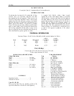
INSTALLATION OF RECEIVER 


Antenna Installation 


In the installation of television receivers the proper 

antenna is a necessity. Successful installations will result 
from attention to details, while slipshod and careless work 
will bring only poor customer satisfaction and repeat 
calls. There is nothing difficult about the installation of 
television aerials, a little patience and experience is all 
that is required. Regular broadcast aerials in the majority 
of cases will be found useless. Impress this upon the 
owner and make a satisfactory installation regardless of 
what other equipment he already has. Satisfactory picture 
reception is what both of you require for the completion 
of the installation. 
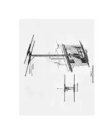
 

The Dipole Antenna 


The Dipole form of aerial is generally satisfactory; it 

consists of two metal rods, each approximately five feet 
long and placed on a line with each other. Extreme 
accuracy in the length of these rods is usually not 
necessary and if the receiver is located very close to the 
transmitting station it may be found advisable to cut down 
the length of each rod. The simple dipole aerial is shown 
in Fig. No, 3. 


 The Lead-In  


The most popular lead-in from the dipole to the 

Television receiver will be a twisted pair as it is 
inexpensive and generally satisfactory in locations where 
the. signal is strong. The length of this lead is usually not 
of extreme importance, It is best to get the Dipole located 
in the clear and as. far from electrical interference as 
possible than to limit its location by using a theoretical 
exact length feeder, The twisted pair should be soldered to 
the lugs on the Dipole as a good connection is essential 
and necessary since several changes in the position of the 
antenna may be required for best results. The other form 
of lead-in is the coaxial line such as the Amphenol  No. 
72. This form of feeder should be used in installations 
where the length of the lead-in is too long for satisfactory 
work with the twisted pair and again where the 
installation is at an extreme distance and every bit of 
energy picked up must be delivered to the receiver. 


Polarization 


If the dipole is mounted horizontally it is said to be 

horizontally polarized, and if vertical it is vertically 
polarized. Since the physical location materially effects 
the aerial no specific form can he advised and we can 
merely suggest that you start by using horizontal 
polarization and change if necessary to produce the best 
results. 


Location of the Antenna 


Whenever possible the Dipole should be erected so 

that it is in line of sight with the transmitter. This does not 
mean that no signals can be secured where a direct view 
of the transmitter cannot be obtained. Surprising results 
are often secured on these high frequencies and no 
concise rules can be assigned to this work. If the location 
is on a street, having heavy traffic there may be 
considerable noise level due to automobile ignition 
systems. In this case, locate the Dipole to the rear of the 
building and away from the source of the noise as far as 
possible. In the case of' electrical machinery over which 
you have no control, the same method can be employed 
along with the utilization of the directional effects of the 
aerial which will be covered later. 


Room Illumination 


Whenever possible the receiver should be so placed 

in the home that a direct glare from either natural or 
artificial light does not fall upon the face of the cathode-
ray tube. The received picture may be viewed under  a 
variety of conditions where it is not always convenient to 
darken the room completely. Adjustments made to meet 
these conditions will not cause damage to the receiver. 
Viewing the pictures in as dark a room as possible is 
always at an advantage as it permits the setting of the 
Intensity and Contrast controls in a manner that will give 
picture tone values more correctly relating to those 
actually used in the studio from which the picture is 
transmitted. 


Installation Process. 


It is a good plan to proceed as follows with the 

installation, 
l. Erect the Dipole antenna in the clear. Start by using 
horizontal polarization (mount the rods horizontal) and 
turn them until their plane is at right angles with the 
location of the transmitter 
2. Adjust the receiver to produce a picture.  
3. Return to the antenna and make final adjustments for 
best signal strength and removal of ghosts, etc. 


Ghost Effects 


Where the picture appears to be duplicated and 

slightly displaced, the additional picture is referred to as 
a ghost. This effect is usually due to the refection of the 
signals and can be cured by the slanting or rotating of the 
Dipole or the use of a reflector or reflectors. If after all 
possible positions have been tried, the ghost still exists it 
will be necessary to change the location of the antenna 
and try again. 


Summary of Contents for 180

Page 1: ......

Page 2: ...ch we believe you will find easy to install and service in spite of the apparent complexity of the subject Television TECHNICAL INFORMATION Frequency Ranges Four Television Channels provided present alignment as follows AUDIO VIDEO STEP STATION SIDEBAND CARRIER CARRIER A NBC Single 49 75 45 25 B CBS Single 55 75 51 25 C D NBC Double 49 75 46 5 Power Ratings Power supply 110 to 120 volts 50 to 60 c...

Page 3: ...e schematic drawings have been provided which due to their size will be found more readable than a single drawing CAUTION AND WARNING The set is equipped with a safety switch which automatically opens upon the removal of the back of the cabinet This protects the operator from dangerous high voltages which would otherwise be exposed The serviceman that is engaged installing or servicing television ...

Page 4: ......

Page 5: ......

Page 6: ...o specific form can he advised and we can merely suggest that you start by using horizontal polarization and change if necessary to produce the best results Location of the Antenna Whenever possible the Dipole should be erected so that it is in line of sight with the transmitter This does not mean that no signals can be secured where a direct view of the transmitter cannot be obtained Surprising r...

Page 7: ......

Page 8: ...ontrol is necessary to properly tune both the sight and sound channels Simply adjust this control until the best reception of the sound is secured and at this point the picture signal will be correctly tuned 4 Marked INTENSITY The intensity or brightness of the picture is controlled by this knob It should be adjusted in conjunction with Control No 1 to get the best picture Note it is a good plan t...

Page 9: ......

Page 10: ...is at D C ground potential As the cathode approaches ground potential due to the discharge of C75 the 6AD5G triode becomes conducting As plate current flows C76 is discharged producing the return trace of the sawtooth The surge of plate current through the winding of the oscillation transformer induces a voltage in the grid winding of proper polarity to drive the grid more positive thereby reducin...

Page 11: ...ning circuits 4 Defective cathode ray tube No modulation 1 Defective or shorted antenna 2 Defect in video receiver 3 Too much bias on modulator electrode 4 Defective cathode ray tube Poor focus 1 Improper voltages supplied cathode ray tube check entire divider circuit 2 Defective video receiver 3 Poor adjustments 4 Defective cathode ray tube Uneven brilliance 1 Hum from power source 2 Defective sc...

Page 12: ...igh resistance values see the component parts list A good voltmeter is also of value and it too should have a high range The Weston Model 722 can be used thus combining both of the above instruments This meter is now equipped with safety prods good insulation is a necessity where high voltages are checked Sensitivity of 20 000 ohms per volt is provided along with a range of 5 000 volts which adds ...

Page 13: ...mately 10 volts peak to peak at an impedance of 5 000 ohms Some of its many uses are as follow 1 Testing overall frequency and phase response of a television receiver 2 Testing ghost response 3 Measuring resolution of cathode ray tubes 4 Adjustment of linearity of horizontal sweep 5 Production of interlaced synchronization for testing interlace and rasters Useful for controlling the Type 202 Telev...

Page 14: ......

Page 15: ......

Page 16: ......

Page 17: ......

Page 18: ......

Page 19: ...00 pot 2 20 2 2 pot pot 1 1 1 2 pot pot pot pot 2 2 pot 2 pot 10 1 1 2 2 pot pot R R W R S W S S S R W R R R R S S R R R R R R R R R R R S S R R R W R R R S R R S R R R R R 200 201 202 203 204 205 206 207 208 209 210 212 213 214 215 216 217 218 219 220 221 222 223 224 225 226 227 228 229 230 231 232 233 234 235 236 237 238 239 240 241 245 246 257 258 500 000 2 000 150 5 000 400 3 000 3 000 3 000 3...

Page 20: ...50 450 450 1500 1500 4000 4000 4000 4000 400 400 50 1500 trimmer trimmer trimmer trimmer variable 400 400 400 400 trimmer 400 400 400 400 214 215 216 217 218 219 220 221 222 223 224 225 226 227 228 229 230 231 232 233 234 235 236 237 238 239 240 241 242 243 244 245 246 247 248 249 250 251 252 253 254 256 257 258 259 260 265 01 01 001 3 30 3 30 3 30 3 30 3 30 3 30 3 30 3 30 L53 L53 L53A L53A T 20 T...

Page 21: ...ction of the receiver AMPLITUDE A term synonymous with gain or size AXIS In television the horizontal plane is called the X Axis and the vertical the Y Axis CATHODE RAY TUBE An evacuated glass tube comprised of a structure for producing and focusing a stream of electrons upon an internal screen COAXIAL CABLE OR LINE A special cable for conveying television signals with as little loss as possible C...

Page 22: ...he technique of dividing the frame into two fields with displaced lines to eliminate flicker INTERACTION A term usually used by designers indicating leakage or the mixing of a signal into another circuit LINE A single line of the 441 comprising the television picture LINEARITY Means uniform rate of motion This is required as the picture will be distorted in non linear portions MODULATION A process...

Page 23: ......

Page 24: ......

Reviews: