Issue 03
Düker GmbH
– www.dueker.de
page 1
Operating Instructions
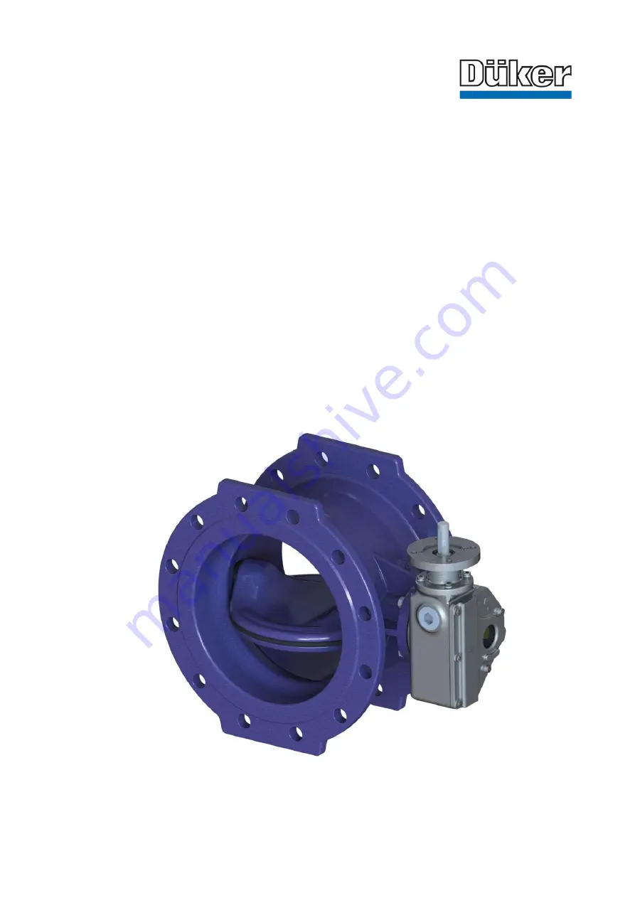
Resilient Seated Butterfly Valves
Type 4510 double flanged
for water/ gas (PN 10/ 16/ 25)
Item no. of the operating instructions: 764848 Issue
03, 2018
, 19
pages
Specifications subject to change without notice


