background image

E-11

3

1

2

INSTALLATION AND CONNECTIONS

This section describes how to set up your projector and how to connect video and audio sources.

To the wall outlet.

Setting Up the Screen and the Projector

Selecting a Location

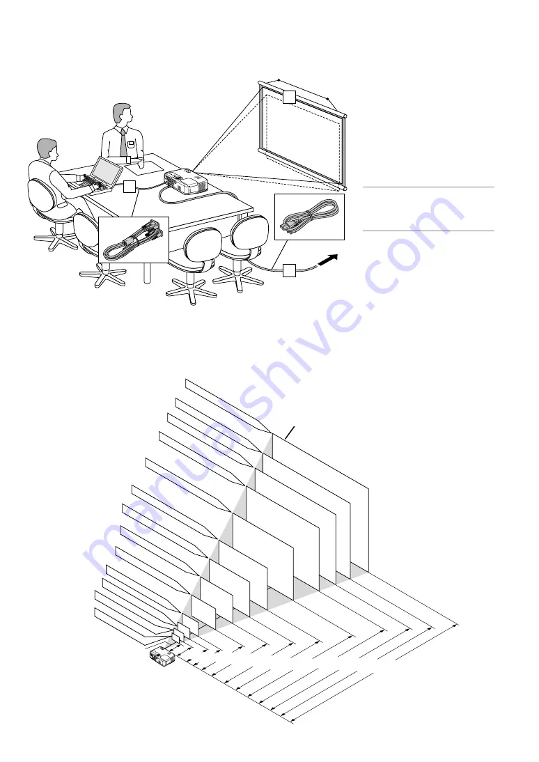
The further your projector is from the screen or wall, the larger the image. The minimum size the image can be is approximately 21" (0.53 m)
measured diagonally when the projector is roughly 27.6 inches (0.7 m) from the wall or screen. The largest the image can be is 300" (7.6 m) when
the projector is about 393.7 inches (10 m) from the wall or screen. Use the drawing below as a guide.

Your projector is simple to set up and use.
But before you get started, you must first:

1

Set up a screen and the projector.

2

Connect your computer or video equip-
ment to the projector. See page
E-13 – 16.

3

Connect the supplied power cable. See
page E-16.

NOTE: 

Ensure that the power cable and any

other cables are disconnected before moving
the projector. When moving the projector or
when it is not in use, cover the lens with the
lens cap.

300"

240"

406.4(W)X304.8(H)/160(W)X120(H)

365.8(W)X274.3(H)/144(W)X108(H)

304.8(W)X228.6(H)/120(W)X90(H)

243.8(W)X182.9(H)/96(W)X72(H)

203.2(W)X152.4(H)/80(W)X60(H)

162.6(W)X121.9(H)/64(W)X48(H)

121.9(W)X91.4(H)/48(W)X36(H)

81.3(W)X61.0(H)/32(W)X24(H)

61.0(W)X45.7(H)/24(W)X18(H)

50.8(W)X38.1(H)/20(W)X15(H)

42.7(W)X32(H)/17(W)X13(H)

Lens center

Screen Size

1.3/51.2" 2.0/78.7" 2.7/106.3"

3.4/133.9" 4.0/157.5" 5.1/200.8" 6.1/240.2"

8.1/318.9"

1.0/39.4"

200"

180"

150"

120"

100"

80"

60"

40"

30"

25"

21"

609.6(W)X457.2(H)/240(W)X180(H)

Screen size (Unit: cm/inch)

487.7(W)X365.8(H)/192(W)X144(H)

6.7/263.8"

Distance (Unit: m/inch)

10.1/397.6"

0.7/27.6"

0.8/31.5"

Summary of Contents for ImagePro 8054

Page 1: ...Liquid Crystal Projector Model 8767 8054 USER S MANUAL...

Page 2: ...the instructions may cause harmful interference to radio communications However there is no guar antee that interference will not occur in a particular installa tion If this equipment does cause harmf...

Page 3: ...e the projector is turned on 2 Do no use the tilt foot for purposes other than originally intended Misuses such as gripping the tilt foot or hanging on the wall can cause damage to the projector 3 Whe...

Page 4: ...2 Getting the Information E 22 USING ON SCREEN MENU E 23 Basic Menu Operation E 23 Using the Menus E 23 List of Menu Items E 24 Menu Elements E 25 Menu Descriptions Functions E 26 Picture E 26 Brightn...

Page 5: ...bPr or any other RGB signals within a horizontal frequency range of 24 to 100 kHz and a vertical frequency range of 50 to 120 Hz This includes NTSC PAL PAL N PAL M PAL60 SECAM and NTSC4 43 stan dard v...

Page 6: ...h When you plug the supplied power cable into an active wall outlet and turn on the Main Power switch the POWER indicator turns orange and the projector is in standby mode See page E 17 Remote Sensor...

Page 7: ...continually it indicates that the lamp mode is set to Eco See the Lamp Indicator section on page E 32 for more details 5 VIDEO Button Press this button to select a video source from a VCR DVD player...

Page 8: ...ni You can use this jack to output sound from the currently selected source RGB VIDEO or S VIDEO Output sound level can be ad justed in accordance with the sound level of the internal speaker 5 S VIDE...

Page 9: ...ted by lighting the PJ button Use this button to enter your menu selection It works the same way as the ENTER button on the cabinet See page E 7 12 CANCEL Right Click Button When you are in the Comput...

Page 10: ...ntrol carefully If the remote control gets wet wipe it dry immediately Avoid excessive heat and humidity If you will not be using the remote control for a long time remove the batteries Do not place t...

Page 11: ...ter or video equip ment to the projector See page E 13 16 3Connect the supplied power cable See page E 16 NOTE Ensure that the power cable and any other cables are disconnected before moving the proje...

Page 12: ...00 4590 5510 5510 6610 6130 7350 6440 7720 7360 8830 8290 9940 9210 11050 mm 130 150 180 250 370 440 490 520 550 610 740 920 1110 1230 1290 1470 1660 1840 mm 533 635 762 1016 1524 1829 2032 2134 2286...

Page 13: ...BM PC or Compatibles Desktop type or Macintosh Desktop type RGB signal cable supplied To mini D Sub 15 pin connector on the pro jector It is recommended that you use a commercially available distribut...

Page 14: ...TVs VCRs and DVD players It is also referred to as Euro connector NOTE The ADP SC1 SCART adapter is obtainable from your dealer in Eu rope Contact your dealer in Europe for more information To RGB IN...

Page 15: ...op tional 15 pin to RCA female 3 cable to connect your DVD player to the RGB IN connector on the projector Component video RCA 3 cable not supplied For a DVD player without component video Y Cb Cr ou...

Page 16: ...o cable not supplied to connect the audio from your VCR or laser disc player to your audio equipment if your VCR or laser disc player has this capability Be careful to keep your right and left channel...

Page 17: ...ortunity to select one of the seven menu lan guages English German French Italian Spanish Swedish and Japa nese To select a menu language follow these steps 1 Use the SELECT G or H button to select on...

Page 18: ...adjustment See page E 19 Move the projector left to center the image horizontally on the screen Adjust the Tilt Foot 1 Lift the front edge of the projector Adjustable Tilt Foot Lever Adjustable Tilt F...

Page 19: ...between 30 de grees upward and 30 degrees downward of projector tilt from level Use the SELECT H button to select Image and then press the SELECT E button The Auto Keystone will be displayed Press th...

Page 20: ...st Clock and Phase manually See page E 28 Turning Up or Down Volume Sound level from the speaker and the AUDIO OUT jack Stereo mini on the projector can be adjusted increase volume decrease volume VOL...

Page 21: ...tion mode between computer and projector The three shaded buttons shown on the drawing work as a computer mouse in the Computer mode In the Computer mode the PJ button is not lit Not lit Works as a mo...

Page 22: ...picture Press again to resume motion FREEZE Enlarging and Moving a Picture You can enlarge the picture up to 400 percent To do so 1 Press the MAGNIFY button to magnify the picture To move the magnifie...

Page 23: ...menu for the item you want to adjust or set 3 Press the SELECT E button or the ENTER button on the remote control or the projector cabinet to select a submenu or item 4 Adjust the level or turn the s...

Page 24: ...AL N PAL60 SECAM Page2 Noise reduction Off Low High Auto Adjust On Off Vertical Horizontal Clock Phase Setup Lamp Mode Normal Eco Language English German French Italian Spanish Swedish Japanese Menu C...

Page 25: ...in a dialog box Select ing on any tab brings its page to the front Radio button Use this round button to select an option in a dialog box Check mark Indicates the item is selected Slide bar Indicates...

Page 26: ...Increases or decreases the color saturation level not valid for RGB Hue Varies the color level from green to blue The red level is used as reference This adjustment is only valid for Video and Compon...

Page 27: ...or your projector to avoid operation by an unauthorized user using the Menu When a keyword is set turning on the projector will display the Keyword input screen Unless the correct keyword is entered t...

Page 28: ...e projector automatically detects a component signal However there may be some compo nent signals that the projector is unable to detect If this is the case select Component Select Scart for the Europ...

Page 29: ...ock and Phase manually Adjusting Position Clock when Auto Adjust is off This allows you to manually adjust the image horizontally and verti cally and adjust Clock and Phase Horizontal Vertical Adjusts...

Page 30: ...ch them as the pieces of glass may cause injury If this happens contact your NEC dealer for lamp replacement To replace the lamp 1 Loosen the lamp cover screw until the screwdriver goes into a free wh...

Page 31: ...lso page E 29 for resetting the filter usage time To replace the filter sponge 1 Remove the filter cover by pushing up on the catch of the cover until you feel it detach 2 Gently peel off the filter s...

Page 32: ...OFF 4 cycle 0 5 sec ON 0 5 sec OFF 6 cycle 0 5 sec ON 0 5 sec OFF Normal Lamp cover error or lamp housing error Temperature error Fan error Lamp error Re firing the lamp Control key locked Replace the...

Page 33: ...t in the menu See page E 29 Reposition the projector to improve its angle to the screen See page E 18 Use the Keystone correction function to correct the trapezoid distortion See page E 19 Adjust the...

Page 34: ...olor Horizontal Resolution NTSC NTSC4 43 PAL PAL M PAL N PAL60 550 TV lines SECAM 350 TV lines YCbCr 800 TV lines RGB dots H 768 dots V External Control RS232 IR Sync Compatibility Separate Sync Compo...

Page 35: ...ound 6 Red Ground Cr Ground 7 Green Ground Y Ground 8 Blue Ground Cb Ground 9 No Connection 10 Sync Signal Ground 11 SCART Sync Sync 12 Bi directional DATA SDA 13 Horizontal Sync or Composite Sync 14...

Page 36: ...95 SGI 1152 900 71 736 76 05 VESA 1280 960 60 60 VESA 1280 1024 63 981 60 02 MAC 1280 1024 69 89 65 2 HP 1280 1024 78 125 72 01 SUN 1280 1024 81 13 76 11 VESA 1280 1024 79 976 75 03 VESA 1280 1024 91...

Page 37: ...ector PC Control Codes Function Code Data POWER ON 02H 00H 00H 00H 00H 02H POWER OFF 02H 01H 00H 00H 00H 03H INPUT SELECT RGB 02H 03H 00H 00H 02H 01H 01H 09H INPUT SELECT VIDEO 02H 03H 00H 00H 02H 01H...

Page 38: ......

Page 39: ...with the product including proper maintenance of air filters Repair or attempted repair by anyone other than a Dukane Corporation authorized service center Any shipment of product claims must be pres...

Page 40: ...Division 2900 Dukane Drive St Charles IL 60174 3395 E mail avsales dukcorp com Phone 630 762 4040 Orders 800 676 2485 Information 800 676 2486 Fax 630 584 5156 Parts Service 800 676 2487 Fax 630 584...

Reviews: