Duerkopp Adler 4260-6 Instructions For Service Manual Download Page 23

20

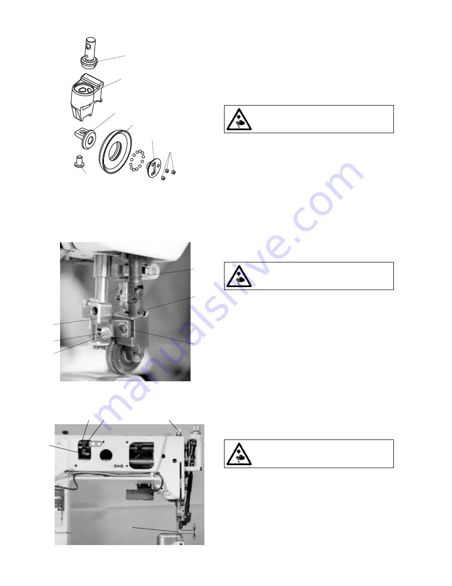
3.7.8.3 Setting the gear clearance

and in the mounting of the top roller

In the cone gear of the drive of the top roller, the minimum

clearance must be set. A too small clearance will increase the

friction resistance of the gear, the excessive clearance will

influence the inaccuracy of feeding. The top roller itself is

mounted on balls. With this type of mounting,it is also

necessary to set the minimal possible radial clearance.

The given clearances are set as follows:

Caution! Danger of injury!

Switch off the main switch! Before starting the setting

operation, wait until the motor stops!

Clearance in the wheel mounting

- Loosen three screws (5) /only slightly/.

- Using the screw  (4) set the minimum clearance in the top

roller mounting (2) /it must easily rotate without any rubbing

and with a minimum clearance/.

- Tighten the screws (5), check the set up clearance, even-

tually, repeat the setting procedure.

Clearance in the conic gear

- Loosen the screw (1), in shifting the wheel, resp. the holder

(3) in the holder groove (6), set  the minimum clearance,

the pinion (7) must be pushed up to the holder bottom (6).

- Tighten the screw (1), check the  set up clearance.

3.7.8.4 Replacement of the top roller

When replacing the top roller, proceed as follows:

Caution! Danger of injury!

Switch off the main switch! Before starting the setting

operation, wait until the motor stops!

- Unscrew the screw (1).

- Unscrew the screw (3) with the washer (2).

- Remove the driven top roller with the holder (4) from the holder

(5) and from the articulated shaft (8).

- Mount another top roller in inverted procedure to dismantling.

- Set the top roller according to the par. 3.7.8.2.

3.8 Setting the top roller lift

The maximum lift of the top roller when lifting the foot with

knee lever or with electromagnet is to be „A“ = 12.5mm.

Caution! Danger of injury!

Switch off the main switch! Before starting the

setting operation, wait until the motor stops!

- Place a cube (1) having the height of „A“ = 12.5 ± 0.7 mm

under the top roller.

- Screw in thoroughly downwards the screw (2).

- Tighten slightly the screw (3) in such a way that the lever (4)

turns on the shaft (5) with a certain friction moment.

- Push with the screwdriver on the lever (4), until it attains

the wall inside the arm of the sewing machine. In this

position, tighten duly the screw (3).

- Check the axial clearance of the shaft (5) which should be

the least possible.

- Set the normal pressure force of the top roller.

4

5

3

2

1

A

6

3

1

4

2

5

4

3

1

2

7

5

6

Summary of Contents for 4260-6

Page 1: ...for service 4260 6 Minerva Boskovice a s Sokolsk 60 CZ 680 17 Boskovice Tel 420 501 453434 453433 494111 Fax 420 501 452165 http www minerva boskovice com Edition 05 2002 Printed in Czech Republic 735...

Page 2: ...les stitch widths with needles side by side 3 5 Thread tensioners and limiter 9 3 5 1 Description 3 5 2 Setting the tension of the main and auxiliary tensioners 3 5 3 Setting the tensioning mechanism...

Page 3: ...ple oil use 4 Thread trimming 25 4 1 Description of the trimming mechanism 4 2 Setting the pickup roller 4 3 Setting the cam 4 4 Setting the fork 4 5 Setting the moving knife 4 6 Setting the fixed kni...

Page 4: ...actions of the operator may lead to dangerous situations In industrial sewing machines Minerva attention should be paid to the following still remaining possible sources of injury 1 Moving sewing need...

Page 5: ...ning the screws 3 and 4 set the required distance A After having set it tighten carefully the screws By axial shifting of the gear wheel 5 set the axial clearance in such a way that this clearance is...

Page 6: ...required clearance between the needle 2 and the protecting sheet 1 When turning to the right the protecting sheet shifts out from the groowe and inversely Check up the protecting effect in pushing aga...

Page 7: ...moment when the hook point comes to lie opposite the needle 4 The wheel 2 is to be set with its gear rim symmetrically to the centre of the gear wheel 1 The clearance between the gear wheels is to be...

Page 8: ...stuck in eye for two threads The connecting rod 2 is mounted on the pin 3 The needle bar holder 4 is mounted through the pin 5 in a rotating way in the arm 6 In its upper part the holder is fastened...

Page 9: ...ion of the take up lever Set the pin of the connecting rod as follows Caution Danger of injury Switch off the main switch Before starting the setting operation wait until the motor stops Remove the fr...

Page 10: ...screw 3 and check up the setting Loosen the screws 4 from the rear side of the post too Shift the post 1 in the right direction in such a way so that both needles pass through the centres of the needl...

Page 11: ...is set 1 2 mm above the bottom edge of the feeding wheel namely according to the hardness of the sewn material Caution Danger of injury Switch off the main switch Before starting the setting operatio...

Page 12: ...y the dynamometer 2 as it is shown on the illustration The size of this force differs according to the category of sewing and is indicated in the par 11 2 The tension of the auxiliary tensioner is reg...

Page 13: ...distance C 3 mm set the angle A 45 and tighten the screw 11 Turn the washers with their noses 7 in such a way that the distance B 3 mm is attained Put the screwdriver into the slit in the bushing 8 a...

Page 14: ...90 on the handwheel 2 and lock it with the screw 5 which is included in the accessory of the machine tighten it carefully Insert the setting stick 3 into the hole in the eccentric 1 and prop it again...

Page 15: ...itch length valid for the given sewing category and the stitch width is attained The scale on the control knob is to be oriented in such a position that the respective maxi mum stitch length on the sc...

Page 16: ...wn work In the position when the wedge is disengaged the star 4 is pushed against the plate 5 lining and at the same time the friction connection with the cover of the clutch 1 is disconnected In this...

Page 17: ...such a way that the shifting of the clutches is done at the moment when the clutch disks 3 do not move which means when they are at the dead center of their oscillating movement This corresponds to t...

Page 18: ...ghten the screw 3 Loosen the screw 5 by 45 1 8 revolution into its original position In this way the optimal clearance of the chain transmission is attained Tighten the screw 4 Correct the set height...

Page 19: ...s for compensating the differences in feeding by the driven top roller and by the lower feed wheeler By turning the screw 12 the change of the gear speed ratio is attained After having set in accordan...

Page 20: ...ng roller of the indented belt of the top feeding is mounted in a rotary way on the bedplate The belt must be ten sioned as needed in such a way that there is ensured the correct function of the trans...

Page 21: ...y that it is possible to remove the indented belt 23 from the arm of the machine Replace the belt with a new one and proceed to the assembly inverted procedure of dismantling Proceed to the setting op...

Page 22: ...the diameter of 25 mm and with the diameter of 35 mm The suitability of the diameter used depends on the type of sewing and on the concrete technological operation There are in general valid the follo...

Page 23: ...1 check the set up clearance 3 7 8 4 Replacement of the top roller When replacing the top roller proceed as follows Caution Danger of injury Switch off the main switch Before starting the setting ope...

Page 24: ...bin the pressing function of the cam on the winders shaft is interrupted and it moves in the sense of the arrow A fine setting is to be done on an incorporated condition in the machine Using the screw...

Page 25: ...n the hook is blocked but the clutch does not disengage the disengaging moment of the clutch is to be reduced in turning the screws to the left Caution The clutch guarantees only one mutual position o...

Page 26: ...h off the main switch Before starting the setting operation wait until the motor stops The belt is correctly tensioned when the opposite sides of the belt approach one to another by up to 20 mm in app...

Page 27: ...s 3 14 2 Refilling oil For lubricating the machine oil Esso SP NK 10 is used or other oil with the same quality When putting the machine into operation each mechanism of the machine is to be lubricate...

Page 28: ...gainst the bracket 5 and at the same time the shaft 2 up to the stop against the shaft 3 With the holder 1 held on the stop shift the shaft 2 in such a way that there appears the gap A 0 2 to 0 4 mm a...

Page 29: ...tch off the main switch Before starting the setting operation wait until the motor stops Loosen the screws 4 and 5 Turn the moving trimming knife 1 in the sense of the arrow and set it in height Tight...

Page 30: ...gory The adjusting screw 2 should not be screwed in in such a way that the retaining spring gets over the perimeter of the moving trimming knife 4 8 Setting the switching of electromagnets The electro...

Page 31: ...way that it enables the maximum stitch length when sewing in forward and in rearward sense If this position is not correct the length of the stitch will be shortened in one or the other feed direction...

Page 32: ...l position sensor The detailed information concerning the drive the control panel and the setting of the position sensor is given in the manual of the drive and of the control panel 9 Lighting 9 1 Mou...

Page 33: ...sewing 3 medium heavy duty sewing 4 heavy duty sewing In the factory where this machine has been manufactured it has been set up with respect to the standard parameters of the required stitch width a...

Page 34: ...number it is necessary to correct the setting of the distance of the shuttle from the needle according to the paragraph 3 1 3 and at the same time the setting of the fixed trimming knife of the trimmi...

Reviews: