Duerkopp Adler 4180-5 Instructions For Service Manual Download Page 21

18

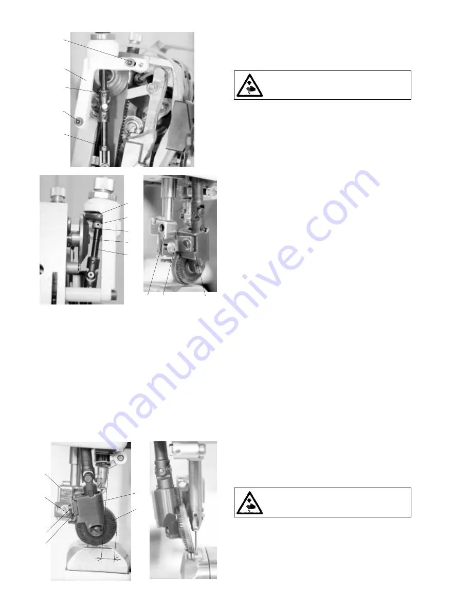
3.6.7 Replacement of friction wheels of the drive

conversion unit

The worn friction wheels (1 and 2) of the drive conversion unit are

to be replaced. This is done as follows:

Caution! Danger of injury!

Switch off the main switch! Before starting the setting

operation, wait until the motor stops!

- Remove the front guard.

- Loosen and unscrew the screw (3) from the holder of the wheel

(4) and remove it from the holder (5).

- Loosen the screws (6 and 7) of the holder (8) and remove the

holder (8) with the telescopic shaft (9) and the driven wheel

from the machine.

- In pulling it out, remove the telescopic shaft (9) from the holder

(8).

- Loosen and unscrew the screw (10) and remove the shaft (11)

with the friction wheel (12) from the telescopic shaft.

- Press out the pin (13) from the shaft (11) and the wheel (12).

- Replace the wheel (12) by a new one and proceed to a reassembly

(an inverse procedure to the dismantling).

- Loosen the screw (14) of the conic friction wheel (15).

- Remove the wheel (15) and replace it.

- Proceed to a reassembly (an inverse procedure to dismantling).

3.6.8 Top  roller
3.6.8.1 Selection of the top roller diameter

The machine can be supplied with two types of top roller,

namely with the diameter of 25 mm and with the diameter of

35 mm. The suitability of the diameter used depends on the

type of sewing and on the concrete technological operation.

There are in general valid the following principles for the

selection of the wheel diameter:

ø


25 mm - for sewing small radii

ø


35 mm - for sewing straight sections or big radii

- for sewing  with great  passages to thicker materials

3.6.8.2 Forward, rearward and side setting

The top roller must be in a defined position in relation to the

needle:

a)view (see Fig. 1) - the value „X“ depends on the diameter of

use top roller (

ø


25 - 6.5 mm; 

ø


35 - 10.5 mm), it is measured

from the the needle bar up to the roller edge when turning

the handwheel to the 180

°

 of the scale against the indicator

b)view (see Fig. 2) - the wheel edge must fit with the edge of

the needle operture at the spot of the needle punch.

These values are to be set as follows:

Caution! Danger of injury!

Switch off the main switch! Before starting the setting

operation, wait until the motor stops!

- Loosen the screw (1).

- By shifting the holder (2) with the top roller (3) in the groove of

the holder (4) set the required value „X“ and tighten the screw(1).

- Loosen the screw (5)

- By shifting the holder (2) in the holder (6) set the bottom edge

of the roller to the edge of the needle operture.

- Tighten the screw (5).

9

7

10

8

6

3

5

11

14

15

13

12

4

X

3

2

6

5

1

4

obr. 2

obr. 1

Summary of Contents for 4180-5

Page 1: ...for service 4180 5 Minerva Boskovice a s Sokolsk 60 CZ 680 17 Boskovice Tel 420 501 453434 453433 494111 Fax 420 501 452165 http www minerva boskovice com Edition 06 2001 Printed in Czech Republic 735...

Page 2: ...nsion of main and auxiliary tensioners 3 4 3 Setting the tensioning mechanism of the main tensioner 3 4 4 Setting the adapting spring 3 4 5 Setting the thread limiter 3 5 Feeding mechanism of the need...

Page 3: ...filling oil 3 13 3 Multiple oil use 4 Threadtrimming 24 4 1 Description of the trimming mechanism 4 2 Setting the pickup roller 4 3 Setting the cam 4 4 Setting the fork 4 5 Setting the moving knife 4...

Page 4: ...actions of the operator may lead to dangerous situations In industrial sewing machines Minerva attention should be paid to the following still remaining possible sources of injury 1 Moving sewing need...

Page 5: ...2 By turning the screws 3 and 4 set the required distance A After having set it tighten carefully the screws By axial shifting of the gear wheel 5 set the axial clearance in such a way that this clear...

Page 6: ...equired clearance between the needle 2 and the protecting sheet 1 When turning to the right the protecting sheet shifts out from the groowe and inver sely Check up the protecting effect in pushing aga...

Page 7: ...at the moment when the hook point comes to lie opposite the needle 4 The wheel 2 is to be set with its gear rim symmetrically to the centre of the gear wheel 1 The clearance between the gear wheels is...

Page 8: ...ic pin 13 with needle bar holder 4 The connecting rod 10 of the needle bar 11 on the loop 12 is mounted in a ball bearing and it is slidingly mounted on the needle bar carrier The mechanism is lubrica...

Page 9: ...w 1 of the pin 2 Loosen the screw 3 of the guide pin 4 In shifting the pin 2 set the needle bar holder on the measure A 7 5 mm distance of the front faces of the arm and of the needle bar holder at th...

Page 10: ...n removing the insert proceed in an inverse sequence 3 3 3 Setting the throat plate and its insert The insert of the throat plate should be set in the machines with the trimming device in such a way t...

Page 11: ...d by the dynamometer 2 as it is shown on the illustration The size of this force differs according to the category of sewing and is indicated in the par 11 2 The tension of the auxiliary tensioner is...

Page 12: ...C 3 mm set the angle A 45 and tighten the screw 11 Turn the washer with the nose 7 in such a way that the distance B 3 mm is attained Put the screwdriver into the slit in the bushing 8 and turn it in...

Page 13: ...ndwheel 2 and lock it with the screw 5 which is included in the accessory of the machine tighten it carefully Insert the setting stick 3 into the hole in the eccentric 1 and prop it against the feedin...

Page 14: ...irst sewing category where the stitch length of the indicator is 3 mm Caution Danger of injury Switch off the main switch Before starting the setting operation wait until the motor stops Screw in the...

Page 15: ...ction connection with the cover of the clutch 1 is disconnected Within a short instant when engaging and disengaging with the carrier plate 5 there are in a friction engagement both the cover 1 and al...

Page 16: ...e shifting of the clutches is done at the moment when the clutch disks 3 do not move which means when they are at the dead center of their oscillating movement This corresponds to the angle 90 on the...

Page 17: ...tained but only to the measure of not deteriorating the beginning of sewing after the carried out thread trimming With every correction of the teeth height the tension of the chain 2 is to be correcte...

Page 18: ...ew 4 Setting the force of the top roller 1 In screwing in the screw 2 the force of the top roller is increased and inversely 3 6 Feeding mechanism of the top roller 3 6 1 Description The starting move...

Page 19: ...etting thereof is to be done as follows Caution Danger of injury Switch off the main switch Before starting the setting operation wait until the motor stops Loosen the screws 1 of the pulley 2 Set the...

Page 20: ...y that it is possible to remove the indented belt 23 from the arm of the machine Replace the belt with a new one and proceed to the assembly inverted procedure of dismantling Proceed to the setting op...

Page 21: ...with the diameter of 25 mm and with the diameter of 35 mm The suitability of the diameter used depends on the type of sewing and on the concrete technological operation There are in general valid the...

Page 22: ...ment of the top roller When replacing the top roller proceed as follows Caution Danger of injury Switch off the main switch Before starting the setting operation wait until the motor stops Unscrew the...

Page 23: ...bin the pressing function of the cam on the winders shaft is interrupted and it moves in the sense of the arrow A fine setting is to be done on an incorporated condition in the machine Using the screw...

Page 24: ...the hook is blocked but the clutch does not disengage the disengaging moment of the clutch is to be reduced in turning the screws to the left Caution The clutch guarantees only one mutual position of...

Page 25: ...h off the main switch Before starting the setting operation wait until the motor stops The belt is correctly tensioned when the opposite sides of the belt approach one to another by up to 20 mm in app...

Page 26: ...e 3 13 2 Refilling oil For lubricating the machine oil Esso SP NK 10 is used or other oil with the same quality When putting the machine into operation each mechanism of the machine is to be lubricate...

Page 27: ...against the bracket 5 and at the same time the shaft 2 up to the stop against the shaft 3 With the holder 1 held on the stop shift the shaft 2 in such a way that there appears the gap A 0 2 to 0 4 mm...

Page 28: ...ch off the main switch Before starting the setting operation wait until the motor stops Loosen the screws 4 and 5 Turn the moving trimming knife 1 in the sense of the arrow and set it in height Tighte...

Page 29: ...egory The adjusting screw 2 should not be screwed in in such a way that the retaining spring gets over the perimeter of the moving trimming knife 4 8 Setting the switching of electromagnets The electr...

Page 30: ...way that it enables the maximum stitch length when sewing in forward and in rearward sense If this position is not correct the length of the stitch will be shortened in one or the other feed direction...

Page 31: ...el position sensor The detailed information concerning the drive the control panel and the setting of the position sensor is given in the manual of the drive and of the control panel 9 Lighting 9 1 Mo...

Page 32: ...ht sewing 2 medium sewing 3 medium heavy duty sewing 4 heavy duty sewing In the factory where this machine has been manufactured the machine has been set with respect to the standard parameters of the...

Page 33: ...h changing the tension of the shuttle thread it is necessary to modify the tension of the retaining spring of the trimming device according to the paragraph 4 7 8 When changing markedly the sewing cat...

Reviews: