Contatto
ModDALI
ModDALI: 4-channel DALI gateway
ModDALI module allows the management, through the
Contatto
bus, of 4 DALI lines upon it's possible to connect
up to 32 devices for line (or channel). In this way it's possi-
ble to control and regulate up to 128 DALI ballasts (or other
similar devices). A firmware special ersion (6.x), available
on request, transforms the module into 2-lines for 64-
ballasts each one; the following refers to the standard
version unless otherwise specified.
ModDALI module performs, for each channel, the following
main features:
all timing functions are accomplished by the module
and it may be controlled by any real or virtual input of
the system, by supervisor or by video terminal
Up/Down and Single commands may be defined for
the manual regulation of lighting level
programmable ramp, in the range 0 to 60 seconds
setting of minimum and maximum output levels
dynamic lights scenes can be easily implemented
through MCP
the current brightness level may be stored and recalled
by the user; up to 16 presets are available to create
“real time” lighting scenes; the preset will be stored in
the non-volatile memory of the ballasts
if a
Contatto
bus failure or DALI bus failure occurs, the
output level will be automatically set to a user-defined
level
diagnostics of short circuit on the DALI lines and lamp
failure, with information about the line where the failure
occurred
galvanic insulation between DALI and
Contatto
buses
The 32 devices for each line can be controlled by:
Line:
each command sent on a line will be executed by all
the devices connected on that same line, therefore all the
related devices will behave in the same way.
Individually:
the commands will be individually sent to each
device, therefore each single device will behave indepen-
dently; for this operation, the DALI devices must be ad-
dressed as described in the following paragraphs.
Groups:
the command will be sent to groups, therefore
each group of devices will behave independently; for this
operation, DALI devices must be addressed and the groups
must be defined as described in the following paragraphs.
The failure of a lamp or ballast can be detected and there-
fore reported only at line level and not individually. Mod-
DALI module can operate exclusively in systems with MCP
controller.
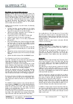
The ModDALI module provides a 5-way terminal blocks for
the connection to
Contatto
bus, a 2-way terminal block for
the supply voltage of DALI section and a 9-way terminal
blocks for the connection to the 4 DALI lines; all terminal
blocks are of removable type. A green LED on the front
panel reports the power-on condition.
On the front panel, four yellow LEDs report the communica-
tion status on the related DALI line; moreover these LEDs
report information about lamp failure and/or lines failure.
Four pushbuttons on the front panel, one for each DALI
line, allow the manual control of connected devices; the
possible functions, through these pushbuttons, are the con-
tinuous regulation of the brightness level and the one-touch
switching on and off.
ModDALI module is housed inside a standard DIN 6M
module for rail mounting.
Address programming
ModDALI module takes 1 output address and, if enabled, 1
input address with the same value (both one made by 4
channels 16-bit).
The address has to be assigned by FXPRO programmer. A
white label on the front panel allows to write the pro-
grammed module address; a check box near to this label
allows to annotate if input address has been enabled or
not.
Operation
ModDALI features 1 output address with 4 channels 16 bit;
each channel is related to one of the 4 DALI lines. Sending
to the output address a code among the available ones
(see following paragraphs), it's possible to perform the de-
sired function.
The easiest way to control each line connected to the DALI
ballasts is by two pushbuttons (Up/Down) or by a single
pushbutton (single command); these pushbuttons can be
connected to any
Contatto
input module and the operation
is like here bottom described.
Up/Down pushbuttons
: pushing and holding the Up (Down)
button, the brightness increases (decreases) until the max
(min) value is reached. When the brightness has reached
the desired level, release the button to hold it.
Single Command:
holding down the button, the brightness
increases until the max value is reached. Releasing and
pushing again the button the brightness decreases to mini-
mum level. Release the button at desired level to hold it.
In addition to these simple manual commands, DALI de-
vices may be controlled by supervisor or by video terminal
(ex. touch screen), simply writing on the output channel the
code of the function which must be executed and to which
ballast must be sent.
DUEMMEGI
s.r.l. - Via Longhena, 4 - 20139 MILANO
Tel. 02/57300377 - Fax 02/55213686 –
www.duemmegi.it
Rel.: 2.4 October 2017
Page 1 of 9


