6.
If measured superheat is:
• more than required, slowly add refrigerant to obtain
required superheat.
• Less than required, slowly recover refrigerant to
obtain required superheat.
NOTE:
Each time charge is added to or removed
from the system, allow the system to run
approximately 15 minutes before
pressure/temperature readings are re-taken
and superheat calculations made.
TXV System Charging
1.
Operate unit for minimum of 10 minutes.
2.
Measure pressure and temperature at liquid valve
service port. Use a good thermistor or electronic
thermometer.
3.
Subtract measured temperature from saturation
temperature (of measured pressure) measured to
obtain subcooling. Refer to
Table 4
for saturation
temperature of R-22.
4.
The subcooling level should be as specified on the unit
specification sheet. In the absence of the specification
sheet, use 12-14°F subcooling.
5.
If measured subcooling is:
• more than required, slowly recover refrigerant to
obtain required subcooling.
• less than required, slowly add refrigerant to obtain
required subcooling.
Defrost System (Heat Pumps Only)
A defrost system consisting of a defrost thermostat
(mounted to the outdoor coil) and a defrost control board
(in the control box) provides automatic defrosting of the
outdoor unit when required. The defrost function is
initiated and terminated based on time and temperature.
During frosting conditions, the compressor will operate for
30, 60 or 90 minutes (field adjustable, factory set for 90
minutes) before switching to the defrost mode.
In geographical areas where heavy snowfall, freezing
rain, or extensive operation in 20°F-40°F range is
expected, the setting should be changed to 30 or 60
minutes. This is performed by relocating the "RUN TIME"
jumper on the defrost board from the pins labelled "90" to
either the "30" or "60" pins.
The defrost board provides a five (5) minute time delay
for compressor short cycle protection. To bypass this
delay, short the two "TEST" terminals together for 2
seconds.
For defrost system checkout, with the system running in
the heating mode, short the two "TEST" terminals together.
The heat pump will go into the defrost mode for as long as
the "TEST" terminals are shorted together.
Unit Maintenance
The unit should be inspected and cleaned on an annual
basis by a qualified technician. This should include
checking for adequate clearances, electrical connections,
duct connections/blockages, air filters, airflow, lubrication,
and operational performance of system.
Coils may
require cleaning. The coil should always be cold when
cleaning. Use an alkaline-based cleaner only.
Cleaning a hot coil or using an acid based cleaner will
remove the paint from the fins and may clog the coil.
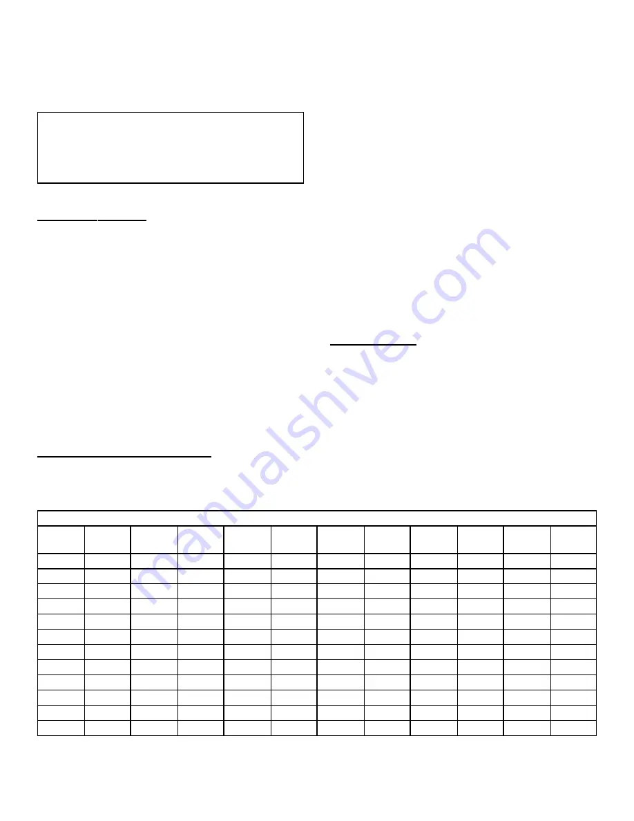
Table 4 - R-22 Saturation Temperature / Pressure Chart
Pressure
(psig)
Temp.
(°F)
Pressure
(psig)
Temp.
(°F)
Pressure
(psig)
Temp.
(°F)
Pressure
(psig)
Temp.
(°F)
Pressure
(psig)
Temp.
(°F)
Pressure
(psig)
Temp.
(°F)
19.3
-6
31.8
9
44.1
21
58.8
33
76.0
45
155.7
85
20.8
-4
32.8
10
45.3
22
60.1
34
77.6
46
168.4
90
22.4
-2
33.7
11
46.4
23
61.5
35
79.2
47
181.8
95
24.0
0
34.7
12
47.6
24
62.8
36
80.8
48
195.9
100
24.8
1
35.7
13
48.8
25
64.2
37
82.4
49
210.8
105
25.6
2
36.7
14
49.9
26
65.6
38
84.0
50
226.4
110
26.4
3
37.7
15
51.2
27
67.1
39
92.6
55
242.7
115
27.3
4
38.7
16
52.4
28
68.5
40
101.6
60
259.8
120
28.2
5
39.8
17
53.6
29
70.0
41
111.2
65
277.8
125
29.1
6
40.8
18
54.9
30
71.4
42
121.4
70
296.7
130
30.0
7
41.9
19
56.2
31
73.0
43
132.2
75
316.5
135
30.9
8
43.0
20
57.5
32
74.5
44
143.6
80
337.4
140
20407502
ISSUE 0144
Page 6 of 8


