


O.D.L - Technical Manual
16
Mounting the Steerer Expander
V2016.10
3.2.2
Installation of the Steerer Expander [Type 2]
Required Material
Specification
Amount
steerer expander
FWXXXXXXXXXX46348S
1
1.
Clean the inner surface of the steerer using a dry cloth.
2.
Apply carbon installation paste in the area of the contact surface between the steerer expander and the
steerer.
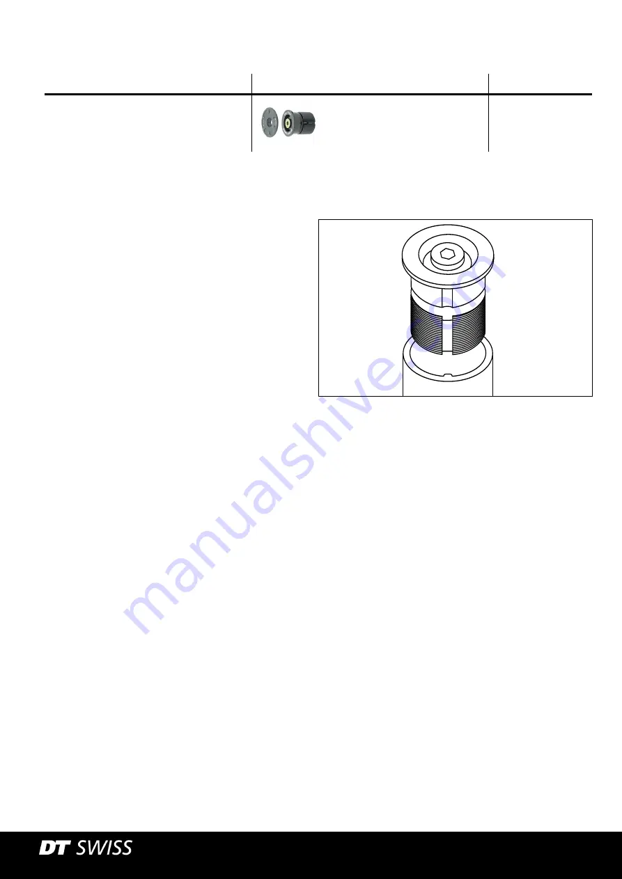
3.
Insert the expander into the steerer up to the
stop.
The expander can only be installed in the
positions specified by the ribs in the steerer.
The grooves on the expander must be aligned
with the ribs in the steerer.
4.
Tighten the screw for the steerer expander to a
maximum torque of 8 Nm.


