439 S Stoddard Ave
San Bernardino, CA 92401
Ph: 1.877.DSPM POWER
1.877.377.6769
Title:
Single Phase
Doc No.: 074
-
3000
-
AEC
Rev: NR
Page#:
-
31
-
Description:
Emergency Lighting Inverter Maintenance Manual
Date: 08/28/2020
Calibration:
Apply power to the system.
Make sure that Bypass Switch (SW1) is in the UPS position and the cover is screwed secure.
Close the input breaker CB1 and then the battery breaker CB2. Verify that each of the following items
takes place:
1.
The fans will come on.
2.
The Processor will perform several series of checks.
3.
The Processor will continue starting the system and the display
’
s (refer to Figure 8) Inverter LED lights.
Note:
The Unit is now on the Inverter.
Record the set values for the system below.
Input Voltage:
L to N __________V, or L1 to L2 __________V
Output Voltage and Current:
L1 to N __________V, L2 to N __________V
L1 __________A, L2 __________A
Note:
all recorded voltages should be measure with True RMS meters.
Operator
’
s
Model:
Location:
Model Number:
S/O Number:
Power Rating and Frequency:
Input Voltage:
Output Voltage:
Enclosure Temperature:
Ambient Temperature:
Test Date:
Installation Date:
Initial Checks:
Set the input Circuit Breaker and the Battery Breaker to the
“
Off
”
position.
Remove all Voltage sources from system while doing the Initial Checks
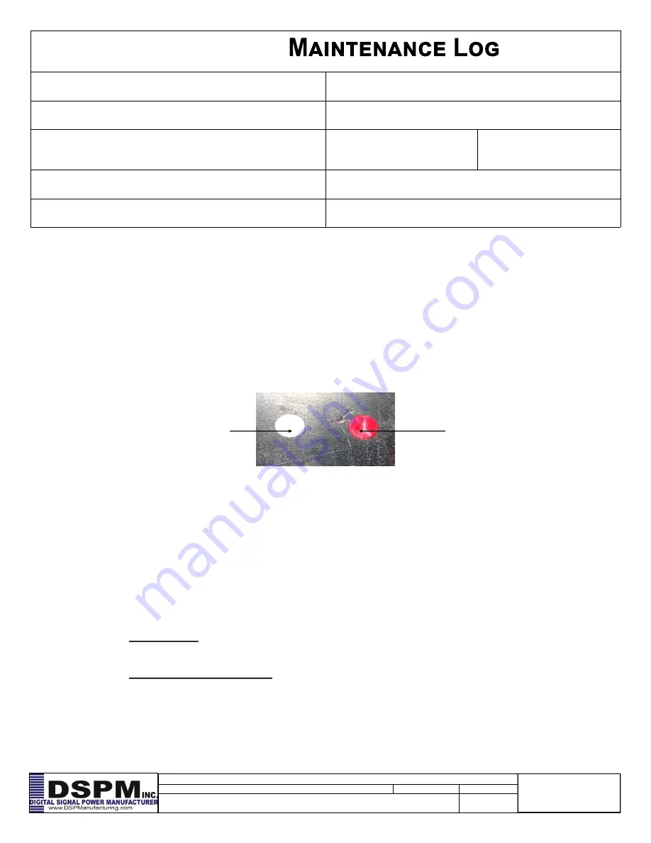
Visually check cabinets for signs of moisture. Check shelf
’
s water dots (see Figure 7). Water dots are
placed on every shelf and door panel to indicate if moisture is present or has got inside the unit. The Dots
are originally white in color but will turn red when water drops are absorbed.
Check cabinets for debris. If found, remove by blowing out cabinet with a non
-
moisture source.
If unit has filter/s, remove and clean.
Check that screws and hardware are secure
Check wire and cable condition
Log 2
Figure 7
Good! No water ever present
Exposed to liquid or water


