background image

6500 Series Control Head Locking Bar Information

The 6500 Series Control Head is built to order based on a direction set up sheet sent with

cabinet on the left for waist high.

“No passage” directions include a fail lock locking bar assembly as well as an unwired solenoid. 

This adds the appropriate parts to the control head to prevent it from rotating in that direction.

“Free passage” (or manual) directions remove the solenoid and locking bar assembly, allowing

the cam to spin freely.

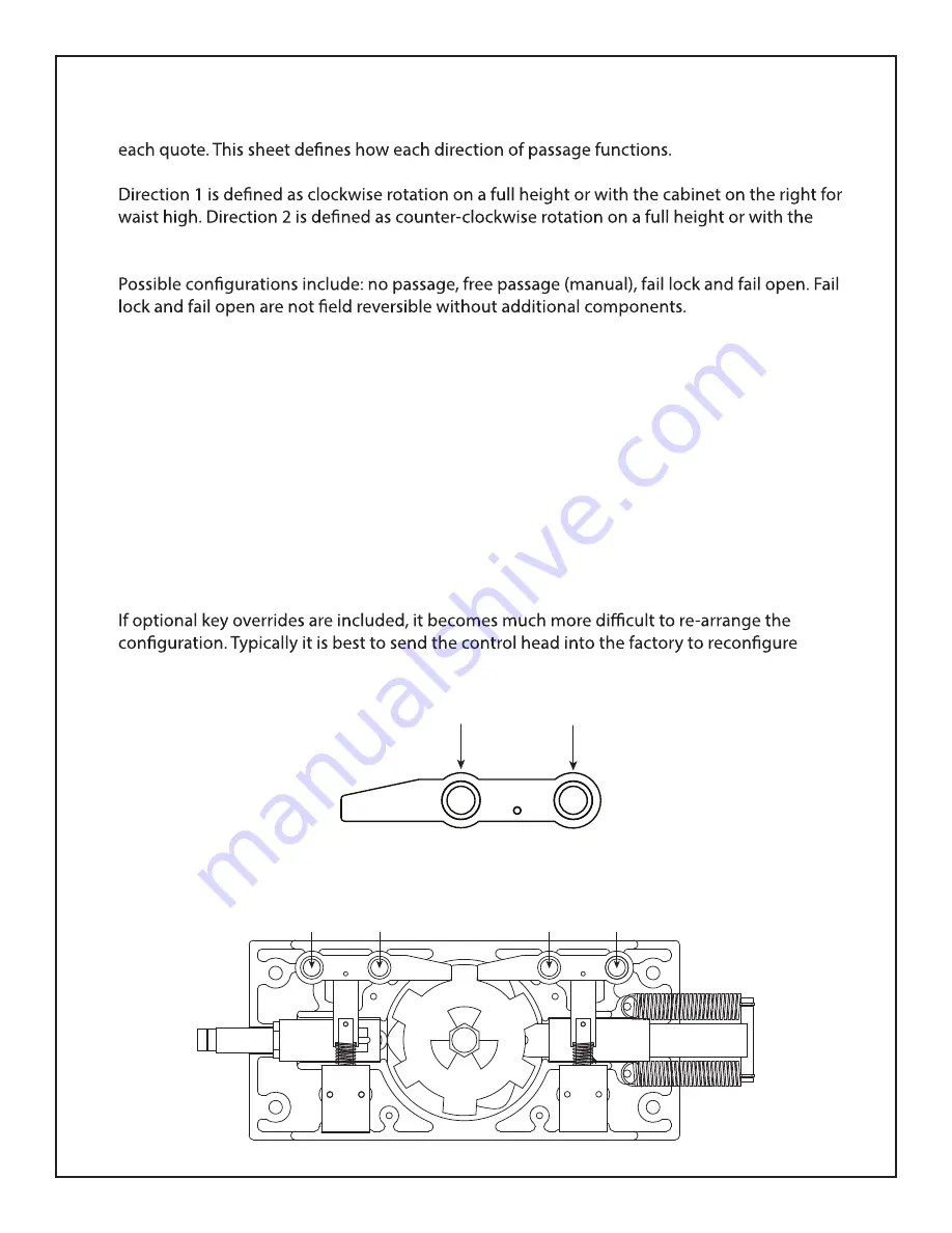
Each direction has a pair of holes on the locking bar and control head casting. These holes

act as pivot points for the locking bar casting. The inner holes are fail lock and outer holes

are fail open. A .5“ dowel pin slides through the entire assembly to hold everything in place.

Alternate linkages and springs are needed to convert a direction’s power failure status.

any key override equipped head to ensure everything is done correctly.

Direction 1 Solenoid

Direction 2 Solenoid

Fail Open

Pivot Point

Fail Lock

Pivot Point

Fail Lock

Pivot Point

Fail Open

Pivot Point

Fail Lock

Pivot Point

Fail Open

Pivot Point

0381

Locking Bar Casting

Hardened 4140 tool steel

casting w/ oil impregnated 

bronze bushings.

512-321-4426

INS-DST80S-190401

Designed Security, Inc - 1402 Hawthorne Street, Bastrop Texas 78602 - (800) 272-3555

[email protected] 

11

Summary of Contents for DST-80

Page 1: ...ion If an installation is done by a construction company or outside installer please pass this book along to the end user This book is required for maintenance troubleshooting repairs 512 321 4426 INS...

Page 2: ...cated near the power supply along with the provided grounding wire from the power supply to ensure the equip ment is properly grounded Do not connect to a receptacle controlled by a switch Feature Lev...

Page 3: ...ion 11 Hydraulic Shock Indexing 13 Electrical Introduction 14 Wiring Diagram 15 Wiring Legend 16 Limit Switch Limit Switch Cam Information 17 Logic Controller Settings 18 Testing Procedure 19 Maintena...

Page 4: ...2 1x Rotor Assembly 3 1x Barrier Assembly 4 2x Curved Yoke Assemblies 5 1x Control Head Assembly 6 1x Fastener Kit 512 321 4426 INS DST80S 190401 Designed Security Inc 1402 Hawthorne Street Bastrop Te...

Page 5: ...d Anchors Qty 1 Bearing Assembly w Hex Shaft Washer Qty 1 10 24 Button Head Cap Screw Barrier to Main Frame Qty 4 3 8 x 1 Bolts w Nuts Washers Lock Washers Control Head to Main Frame Qty 1 Liquid Grou...

Page 6: ...eath and pour epoxy grout into each of the 5 holes Allow epoxy to cure before removing blocks 8 Once the epoxy has cured remove the blocks from under the curved yokes and stationary barrier Thread the...

Page 7: ...hed in the case of an electronic two way control head In this instance each rotational per valid entry request Our anti backup cams are designed so that it is mechanically impossible to become trapped...

Page 8: ...512 321 4426 INS DST80S 190401 Designed Security Inc 1402 Hawthorne Street Bastrop Texas 78602 800 272 3555 sales dsigo com 8...

Page 9: ...es 6535 WH 427 430 T80 ADA 6541 439 448 P60 HD Control Head Bearings Indexing Springs 1106 Waist High Light 1108 Full Height Heavy 1107 ADA Extra Heavy Solenoid Springs 6510 Fail Open Spring 6016 Fail...

Page 10: ...ring and exiting a facility Fail lock Upon power failure an electronically controlled direction would remain locked methods of exiting are available Unless equipped with key overrides this is can be e...

Page 11: ...ting These holes act as pivot points for the locking bar casting The inner holes are fail lock and outer holes are fail open A 5 dowel pin slides through the entire assembly to hold everything in plac...

Page 12: ...e diameter is 041 6518 Fail Lock Linkage These have an approximate length of 2 25 and also include an extra hole the key override option 6010 Fail Lock Solenoid Spring These look the same as the fail...

Page 13: ...l are facing upright Some models may require an additional turn or two outward if the arm does not self center on even the lowest setting 1 Hydraulic Shocks Setting Loosen the set screw on the head of...

Page 14: ...r inputs just like all previous generations so any installation is compatible in one way or another If assistance is needed with understanding how to convert the wiring from access control to the new...

Page 15: ...ion 2 Access Control Relay N O COM Direction 1 Override Relay N O COM Direction 2 Override Relay N O COM Black Black Brown Brown Blue Blue White not used White not used Optional Direction 1 LED Indica...

Page 16: ...Uses black output wire from light s cable Red Light An indicator to inform pedestrians that the unit is locked or that pedestrians require credentials to enter Uses brown output wire from light s cab...

Page 17: ...home position which re engages the locking bar The cam is still free to move until it swings back to the home position Turnstile control heads use a triangular shaped limit switch cam One point of th...

Page 18: ...inputs Toggle Direction 1 by pressing and Direction 2 by pressing This should be set to On in almost every installation number of access control requests the unit will allow in queue Each value can b...

Page 19: ...ntrol either access control is not connected properly is normally closed instead of normally open or is access control system If the unit successful unlocks but does not re lock upon rotation try to m...

Page 20: ...n belief stainless steel is not rust proof Exposure to certain chemicals and harsh environments such as ocean air or chemical plants may cause surface corrosion Minor discoloration can be removed with...

Page 21: ...wiring is correct try to disconnect the solenoids from outputs 01 04 If system stops cycling replace faulty solenoid Turnstile powers up but does not respond Improper wiring from access control to log...

Page 22: ...e are becoming trapped inside of the turnstile Full Height models Rotor was installed backwards Refer to page 4 installation for visual diagram on how to install rotor properly Turnstile only rotates...

Page 23: ...port explanations Refer to page 11 for more information Additional parts will be required to convert operation The control head can be returned labor plus parts if required Please contact us before r...

Page 24: ...cing the user to back out of the turnstile There are timer settings for adjusting how long it takes for this to occur The default time provided is 7 seconds The reason for this is in case somebody swi...

Page 25: ...in material and workmanship when properly installed used and maintained according to instructions DSI will for a period of one 1 year three 3 years for Optical Turnstiles from date of purchase repair...

Reviews: