background image

10. Programming

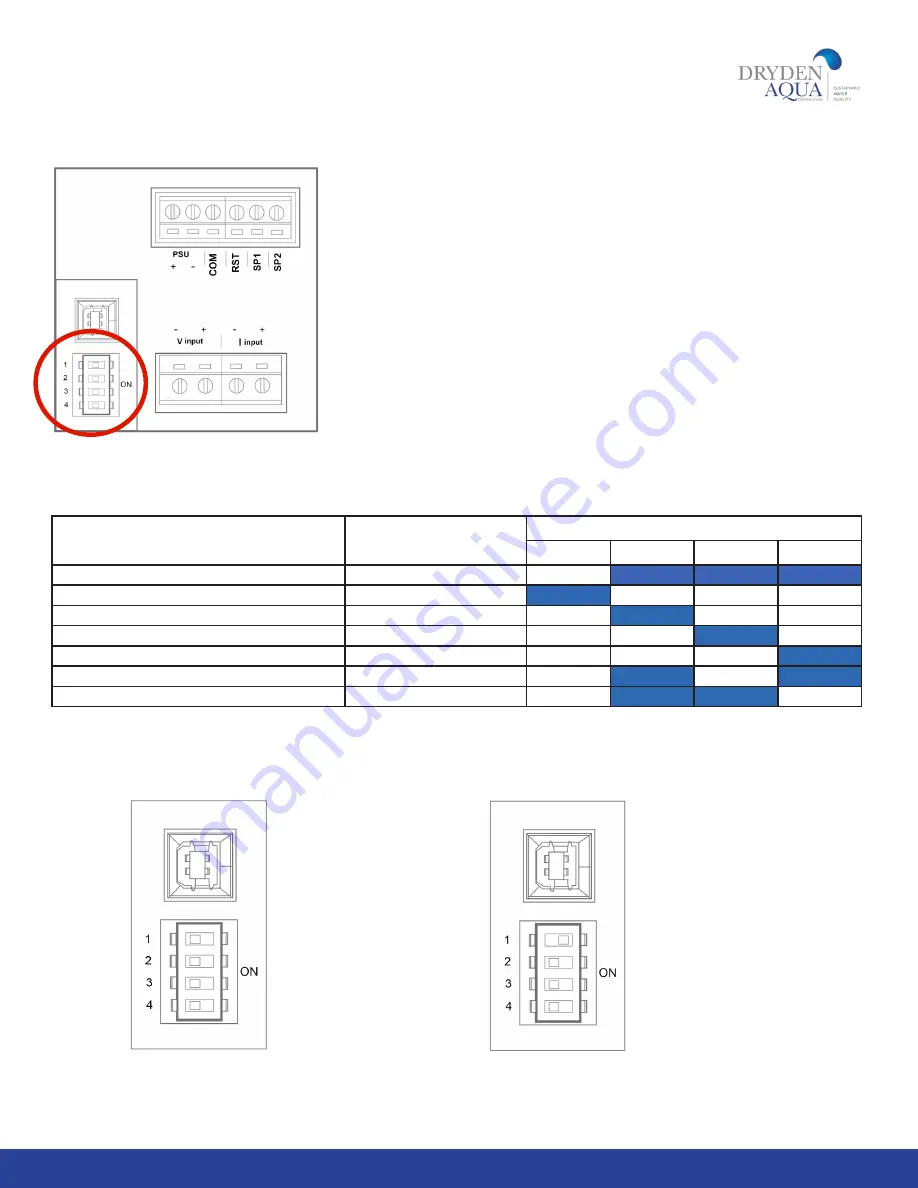
To proceed with programming, first locate the DIP switches on the back side 

of the Digital display. Refer to the circled area in Fig.3.2.

Important Note: It is important to select the correct DIP switch position 

based on BOTH the model (first column) and the pipe size (second column) 

shown in the table below as multiple FlowVis models exist for the same pipe 

diameter.

11

Fig 3.3 (left) The 

default setting for 

the DIP switches (all 

switches set to the 

OFF position).

Fig 3.4 (left) DIP 

switch number 1 set 

to the ON position.

Fig 3.2


     WWW.DRYDENAQUA.COM

Flowvis model / reference #

Pipe size

DIP - Switch position

1

2

3

4

d 50mm / ref 90020

DN40 / d50mm / 1.5”

OFF

ON

ON

ON

d 63mm / ref 90021

DN50 / d63mm / 2”

ON

OFF

OFF

OFF

d 75mm / ref 90026

DN65 / d75mm / 2.5”

OFF

ON

OFF

OFF

d 90mm / ref 90022

DN80 / d90mm / 3”

OFF

OFF

ON

OFF

d 110mm / ref 90023

DN100 / d110mm / 4”

OFF

OFF

OFF

ON

d 160mm / ref 90027

DN150 / d160mm / 6”

OFF

ON

OFF

ON

d 200mm / ref 90028

DN200 / d225mm / 8”

OFF

ON

ON

OFF

Summary of Contents for 90020

Page 1: ...FlowVis digital WWW DRYDENAQUA COM IMPORTANT NOTE For the most up to date version of this manual please visit www drydenaqua com downloads English Rev 1 3 10 2020 OPERATING MANUAL EN EN ...

Page 2: ...ns 5 Pre Installation 5 Installation 6 Wiring 9 Output 10 Programming 11 Operation 12 Advanced Setup 12 Auxiliary Relay 15 Display Features 16 Troubleshooting 17 Environmental 18 Standards Approvals 18 Specifications 19 Warranty back cover 2 SECTION 1 2 3 4 5 6 7 8 9 10 11 12 13 14 15 16 17 18 20 ...

Page 3: ...vanced Setup features FlowVis Digital can be interfaced with other systems such as heaters chemical feeders and UV units so that they will only operate above a user defined flow rate When using this option it will be necessary to include the Auxiliary Interface Unit with your purchase FlowVis Digital also includes a 4 20 mA output that can be interfaced to Variable Frequency Drives such as H2flow ...

Page 4: ...national adapters for export markets Fig 1 1 NEMA 4X enclosure with pre mounted Display and cable glands Equipment and accessories not included in the FlowVis digital FV D box Fig 1 6 Optional 8M 26 25ft extension cable Fig 1 7 Optional Auxiliary Interface Unit Fig 1 5 Type A to Type B cable Fig 1 4 For 1 5 DN40 2 DN50 2 5 DN65 FlowVis models New flapper with attached indicator arm with magnet ...

Page 5: ...s to you please refer to Installation section 6 1 before proceeding to Installation section 6 3 b Install FlowVis Digital to a 3 DN80 or 4 DN100 FlowVis that was manufactured before November 2020 If this section applies to you please refer to Installation section 6 2 before proceeding to Installation section 6 3 If your FlowVis 3 DN80 or 4 DN100 was manufactured after March 2020 please proceed dir...

Page 6: ... however it is important to reassemble the unit exactly as shown below Spring legs location tabs Procedure 1 Release each of the two spring legs from the location tabs this will remove the tension from the spring See Fig 2 3 above 2 Slide the Hasteloy pivot pin to completely remove it from the lid 3 Discard the existing gray Flapper with its attached red indicator 4 Pay attention to the orientatio...

Page 7: ...he top of the FlowVis scale should be toward the direction of flow 6 Referring to Fig 2 5 right identify the required side of the FlowVis to mount the FlowVis sensor ensuring that the sensor is fully seated and the screw holes line up with those on the FlowVis lid assembly 7 Place 6 of the 8 FlowVis screws in the lid assembly and use the 2 longer screws provided with your FlowVis Digital Fig 1 3 o...

Page 8: ...en the screws Do not fully tighten either screw before proceeding to the next i e pull them down slowly multiple times to avoid stressing and cracking the sensor Screws should be tighteneed to a final torque of 25 in lbs or 2 8 Nm Disclaimer Under no circumstances should the screws in the FlowVis lid assembly or sensor be tightened with an electric screwdriver in the drill setting This can result ...

Page 9: ...9 8 Wiring Power Supply Wiring Fig 2 7 Fig 2 8 Sensor Wiring WWW DRYDENAQUA COM ...

Page 10: ...10 9 Output Auxiliary Relay Wiring Fig 3 1 4 20 mA Wiring Fig 2 9 Auxiliary Relay External Equipment Connection COIL Fig 3 0 10 ...

Page 11: ...iameter 11 Fig 3 3 left The default setting for the DIP switches all switches set to the OFF position Fig 3 4 left DIP switch number 1 set to the ON position Fig 3 2 WWW DRYDENAQUA COM Flowvis model reference Pipe size DIP Switch position 1 2 3 4 d 50mm ref 90020 DN40 d50mm 1 5 OFF ON ON ON d 63mm ref 90021 DN50 d63mm 2 ON OFF OFF OFF d 75mm ref 90026 DN65 d75mm 2 5 OFF ON OFF OFF d 90mm ref 90022...

Page 12: ...e advanced setup procedures These features comprise Display of the pool turnover rate Changing the display s appearance at a user defined flow rate Programming an optional auxiliary relay to operate external equipment such as a Heater or Chemical Feed System which will only operate at user defined flow rates Programming the advanced features will require a Windows based laptop PC The initial step ...

Page 13: ...n Click on the Configurator Download button When the Configurator has finished downloading open the file either from your Downloads folder or from the bar at the bottom of your browser Follow the prompts provided by the Setup Wizard and when asked click on Save As Save the file to your preferred location The default file name will be APM Configurator After downloading the file double click on the ...

Page 14: ...cklight box and selecting the desired appearance When all changes have been made it is essential that you click on APM in the menu at the top of the screen and then click on the dropdown option Write Configuration to APM Before disconnecting the Type A to Type B cable between your PC and the Display you may wish to save your configuration settings To do so click on File at the top left of the Conf...

Page 15: ...C coil and 2 sets of souble pole double throw dry contacts 1 Set of relay coil wires 1 Cable zip ties 2 with 1 adhesive pad 6 Crimp style Cable Spades 1 Cable Gland Installation internal 1 Secure Relay by removing adhesive backing tape 2 Attach pre made blue wire to terminal 1 on Relay 3 Attach pre made red wire to terminal 0 on Relay 4 After removing protective film attach Cable Pad to rear of hi...

Page 16: ...ese are normally open contacts that will close when the relay coil is energized by the setting applied in the Advanced Setup section on page 14 14 Display features The FlowVis Digital Display comprises certain standard features as well as user defined parameters adjustments Standard features include a Digital and Bar Graph reading of the measured flow rate The user has the option to program the Un...

Page 17: ...rminals if yes Check to see if power source is active If yes Power Supply needs to be replaced Digital Display reads zero flow rate with pump running Is Display illuminated If yes Check to see if FlowVis is reading the expected flow If yes Check to see if there is a steady blue light on the sensor If no Check sensor wiring and terminations into the rear of the Display red wire to I input black wir...

Page 18: ...ease contact Dryden Aqua for further guidance Turnover rate appears to be inaccurate The turnover rate is calculated by the programmed pool volume divided by the flow rate Perform a manual calculation as follows Pool Volume Flow Rate from FlowVis 60 Turnover rate in hours If this number is different to the value shown on the FlowVis Display reconnect your laptop and check that the pool volume has ...

Page 19: ...Socket 25 feet 7 62M long Power Supply Power Connection Receptacle style Power Source 100 240VAC 0 4 Amps Power Output 12 VDC 1 0 Amps Low Voltage Cable Length 10 3M Auxiliary Relay Output Contacts Double Pole Double throw Form C Dry Contacts Contact Ratings 20A max Relay Coil 12VDC sourced and controlled by the Display Analog Output 4 20mA Scaled to 4 mA zero flow 20 mA max flow rate limit of ins...

Page 20: ...eakage of a FlowVis Digital sensor or FlowVis lid due to the over tightening of lid screws damage to the FlowVis Digital LCD display screen due to misuse or excessive exposure to chemicals the splicing or cutting of cables or wires unless explicitly instructed to do so during the installation process or the installation of an indoor rated FlowVis Digital enclosure in an outdoor environment Charges...

Reviews: