background image

Page 9

SKU 96526

For technical questions, please call 1-800-444-3353.

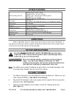
SpECIFICAtIOnS

Electrical Requirements

Charger Input:  120 V~ / 60 Hz

Charger Output:  24 VDC / 400mA

Battery Type:  1300 mAh Ni-Cd Rechargeable

Charge Time:  3 to 5 Hours

Power Cord Type:  22 AWG x 2C

Drill Speed

Dual Speed

Drill RPM:  0~400 RPM (#1 Setting) / 0~1050 RPM (#2 Setting)

Chuck Type

1/2” Keyless

Settings

20 Clutch Settings / 1 Drill Setting

Additional Features

Reversible Rotation

Accessories

Battery (Qty. 1) / Charger (Qty. 1)

Double ended Screwdriver Bits (Qty. 2)

Drill Dimensions

9-1/2” L x 3-1/” W x -1/” H (Without Battery)

Net Weight

4.2 Pounds

unpACkIng

When unpacking, check to make sure that the item is intact and undamaged.  if 

any parts are missing or broken, please call Harbor Freight Tools at the number shown 

on the cover of this manual as soon as possible.

SEt-up InStRuCtIOnS

Read the EntIRE IMpORtAnt SAFEtY InFORMAtIOn section at the 

beginning of this manual including all text under subheadings therein 

before set up or use of this product.

Risk of accidental starting; resulting in serious personal 

injury.  turn the power Switch of the tool to its “OFF” 

position and unplug the tool from its electrical outlet before 

assembling or making any adjustments to the tool.

note:

  For additional information regarding the parts listed in the following pages, refer 

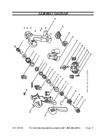
to the Assembly Diagram near the end of this manual.

to Charge the Battery

The Battery (29) does not come charged from the manufacturer.  Before use, you 

must charge the Battery.  

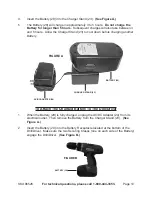
(See Figure A, next page.)

Plug the AC/DC Adapter’s (24) 2-prong plug into the nearest 120 volt, grounded, 

electrical outlet.  

(See Figure A.)

insert the AC/DC Adapter’s (24) charge cord into the Charger Stand (23). 

(See Figure A.)

1.

2.

3.

WARnIng

WARnIng

Summary of Contents for DRILL MASTER 96526

Page 1: ... 3491 Mission Oaks Blvd Camarillo CA 93011 Visit our website at http www harborfreight com Read this material before using this product Failure to do so can result in serious injury Save this manual Copyright 2007 by Harbor Freight Tools All rights reserved No portion of this manual or any artwork contained herein may be reproduced in any shape or form without the express written consent of Harbor...

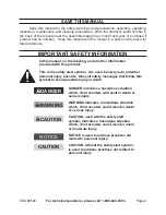
Page 2: ... the safety alert symbol It is used to alert you to potential personal injury hazards Obey all safety messages that follow this symbol to avoid possible injury or death DANGER indicates a hazardous situation which if not avoided will result in death or serious injury WARNING indicates a hazardous situation which if not avoided could result in death or serious injury CAUTION used with the safety al...

Page 3: ...body contact with earthed or grounded surfaces such as pipes radiators ranges and refrigerators There is an increased risk of electric shock if your body is earthed or grounded Do not expose power tools to rain or wet conditions Water entering a power tool will increase the risk of electric shock Do not abuse the cord Never use the cord for carrying pulling or unplugging the power tool Keep cord a...

Page 4: ...if the switch does not turn it on and off Any power tool that cannot be controlled with the switch is dangerous and must be repaired Disconnect the plug from the power source and or the battery pack from the power tool before making any adjustments changing accessories or storing power tools Such preventive safety measures reduce the risk of starting the power tool accidentally Store idle power to...

Page 5: ...against your body is unstable and may lead to loss of control The battery charger gets hot during use The charger s heat can build up to unsafe levels and create a fire hazard if it does not receive adequate ventilation due to an electrical fault or if it is used in a hot environment Do not place the charger on a flammable surface Do not obstruct any vents on the charger Especially avoid placing t...

Page 6: ...and work with approved safety equipment such as those dust masks that are specially designed to filter out microscopic particles California Health Safety Code 25249 5 et seq The warnings precautions and instructions discussed in this instruction manual cannot cover all possible conditions and situations that may occur It must be understood by the operator that common sense and caution are factors ...

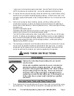
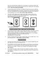
Page 7: ...ble Insulated Tools Tools with Two Prong Plugs Tools marked Double Insulated do not require grounding They have a special double insulation system which satisfies OSHA requirements and complies with the applicable standards of Underwriters Laboratories Inc the Canadian Standard Association and the National Electrical Code See Outlets for 2 Prong Plug Double insulated tools may be used in either of...

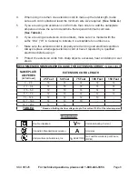
Page 8: ...ctrical condition Always replace a damaged extension cord or have it repaired by a qualified electrician before using it Protect the extension cords from sharp objects excessive heat and damp or wet areas RECOMMENDED MINIMUM WIRE GAUGE FOR EXTENSION CORDS 120 240 VOLT NAMEPLATE AMPERES at full load EXTENSION CORD LENGTH 25 Feet 50 Feet 75 Feet 100 Feet 150 Feet 0 2 0 18 18 18 18 16 2 1 3 4 18 18 1...

Page 9: ...r shown on the cover of this manual as soon as possible Set Up Instructions Read the entire Important Safety Information section at the beginning of this manual including all text under subheadings therein before set up or use of this product Risk of accidental starting resulting in serious personal injury Turn the Power Switch of the tool to its OFF position and unplug the tool from its electrica...

Page 10: ... cool down before charging another Battery BATTERY 29 AC DC ADAPTER 24 CHARGER STAND 23 FIGURE A To Attach The Charged Battery To The Drill Driver When the Battery 29 is fully charged unplug the AC DC Adapter 24 from its electrical outlet Then remove the Battery from the Charger Stand 23 See Figure A Insert the Battery 29 into the Battery Receptacle located at the bottom of the Drill Driver Make s...

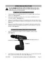
Page 11: ...l including all text under subheadings therein before set up or use of this product To Operate The Forward Reverse Switch The three position Forward Reverse Switch 7 is located on top of the Power Switch 10 See Figure C When the Forward Reverse Switch 7 is in the center the Drill Driver is in a LOCKED position See Figure C When the Forward Reverse Switch 7 is pressed to the right the rotation of t...

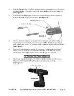
Page 12: ... place to tighten the Chuck around the drill bit or screw driver shaft Make sure the drill bit or screw driver is seated securely before operation See Figure D Push the Forward Reverse Switch 7 to the right Gently press the Power Switch and note whether the bit wobbles while it rotates If the bit wobbles release the power switch repeat steps 1 through 5 to reposition bit To Operate The Torque Sele...

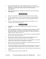
Page 13: ... Driver Do not apply excessive pressure to the Drill Driver while drilling If the speed of the tool drops abnormally decrease the pressure immediately If the drill bit stops abruptly or the bit becomes blocked release the Power Switch 10 at once Ensure the safety of the work space Clear the work area of all parts and debris that may cause injury by flying objects Before drilling clamp the object d...

Page 14: ...nce or cleaning procedures Damaged equipment can fail causing serious personal injury Do not use damaged equipment If abnormal noise or vibration occurs have the problem corrected before further use CAUTION Always disconnect the Battery 29 from the tool before performing and inspection maintenance or cleaning Before each use examine the general condition of the Drill Driver Check for loose screws ...

Page 15: ...Contact local hazardous waste disposal authorities for proper Battery disposal Never set fire to a used Battery Keep the Drill Driver exterior free of oil and grease Use only a mild detergent and damp cloth when cleaning Do not use a flammable or combustible solvent Do not immerse this tool in a liquid or allow a liquid to flow inside the tool WARNING If the supply cord of this power tool is damag...

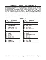
Page 16: ...ssumes all risk and liability arising out of his or her repairs to the original product or replacement parts thereto or arising out of his or her installation of replacement parts thereto PARTS LIST Part Description 1 Keyless Chuck 2 Compression Leaf 3 Torque Setting Ring 4 Scatter Heat Block 5 Orientation Block Up 6 Orientation Block Down 7 Forward Reverse Switch 8 Sheve Block 9 Spring 10 Power S...

Page 17: ...Page 17 SKU 96526 For technical questions please call 1 800 444 3353 ASSEMBLY DIAGRAM CARRYING CASE 36 NOT SHOWN ...

Page 18: ...l or consequential damages arising from the use of our product Some states do not allow the exclusion or limitation of incidental or consequential damages so the above limitation of exclusion may not apply to you This warranty is expressly in lieu of all other warranties express or implied including the warranties of merchantability and fitness To take advantage of this warranty the product or par...

Reviews: