DVJ WHISPAIR
™
Dry Exhauster
|
5
INSTALLATION
The DVJ blower should have a full-sized silencer installed
on the discharge and a minimum length of full size piping,
if necessary, for the installation. Back pressure created by
silencer restriction and pipe losses reduces the jet inlet flow
and increases blower temperature rise. No valves should be
used in the discharge piping.
The 1016 and 1220 blower has a temporary cover installed
on one cylinder slot inlet port at the factory and a permanent
metal cover on the other. A full size acoustic absorption type
silencer should be installed in place of the temporary cover,
however, the cover and silencer may be reversed on the
cylinder slot plenum ports if the installation requires it. Some
type of protection such as a filter screen is necessary to
stop foreign particle entry through the cylinder slots. Outside
installations may also require some weather protection to
prevent the entry of rain or snow. Jet inlet restriction will
cause an increase in blower temperature rise and should
be checked as a possible cause if temperature rise limits
operation to a vacuum level less than maximum allowable.
Technical assistance at installation by a factory Service
Engineer is usually not required for the smaller units, frame
series 1000 through 1400. Workmen with general experience
in installing heavy machinery should be able to complete
a satisfactory installation. Information in this manual is
supplemented by the more detailed discussions of founda-
tions and piping in API recommended practice 686 and
the Compressed Air and Gas Handbook, published by the
Compressed Air and Gas Institute, New York City and the
American Petroleum Institute, Washington, D.C. However, a
Service Engineer may be employed for assistance or for final
checking of an installation.
Handling of the equipment should be accomplished by
methods conforming to safe practice for the weight involved.
Weight of a bare unit, without base plate, driver or acces-
sories will range from about 1 ton (910 kg) for the smallest to
approximately 7 tons (6350 kg). On such units, an eyebolt is
provided near each end for lifting. A unit mounted on a base
plate should be lifted only by the four lifting lugs provided.
Weight in this case will be greater than the following figures.
Before lifting with eyebolts, test one for tightness and
fractures by tapping with a hammer. Direction of pull on the
bolts during lift should be nearly vertical. Since a considerable
cable angle will usually be unavoidable, place a stiff spreader
between the eyebolts to take the side strain, and adjust cable
lengths so that the unit is approximately level during the lift.
A harness featuring four lifting hooks is required to lift
base-mounted units. After inserting the hooks in the lifting
lugs, block the chains out on the sides to avoid placing the
unit under strain. At the same time, adjust lengths to produce
a level lift.
LOCATION
of the installation is generally not a critical matter.
A clean, dry and protected indoor location is to be preferred.
However, an outdoor location will give satisfactory service
if correct lubrication for expected temperatures is provided.
Effect of such a location on driver and other equipment must
also be considered.
PROTECTION
of internal machined surfaces against normal
atmospheric corrosion is normally provided at the factory,
using a vaporizing inhibitor. Markings on the flange covers will
indicate this protection. Maximum period of protection is one
year under average conditions, if flange covers and closing
seals are not removed.
Protection against chemical or
salt water atmosphere is not provided.
Leave covers
and tape seals over all openings as long as possible during
installation to avoid loss of protection.
If there is to be an extended period between installation
and start up, the following steps should be taken to insure
corrosion protection:
1. Coat internal of gearbox and drive end bearing covers
with a vapor phase rust inhibiting liquid such as Nox-
Rust VCI-10. Use Zerust vapor capsules in the inlet port
of cylinder. Repeat once a year or as conditions may
require. VCI-10 is oil soluble and does not have to be
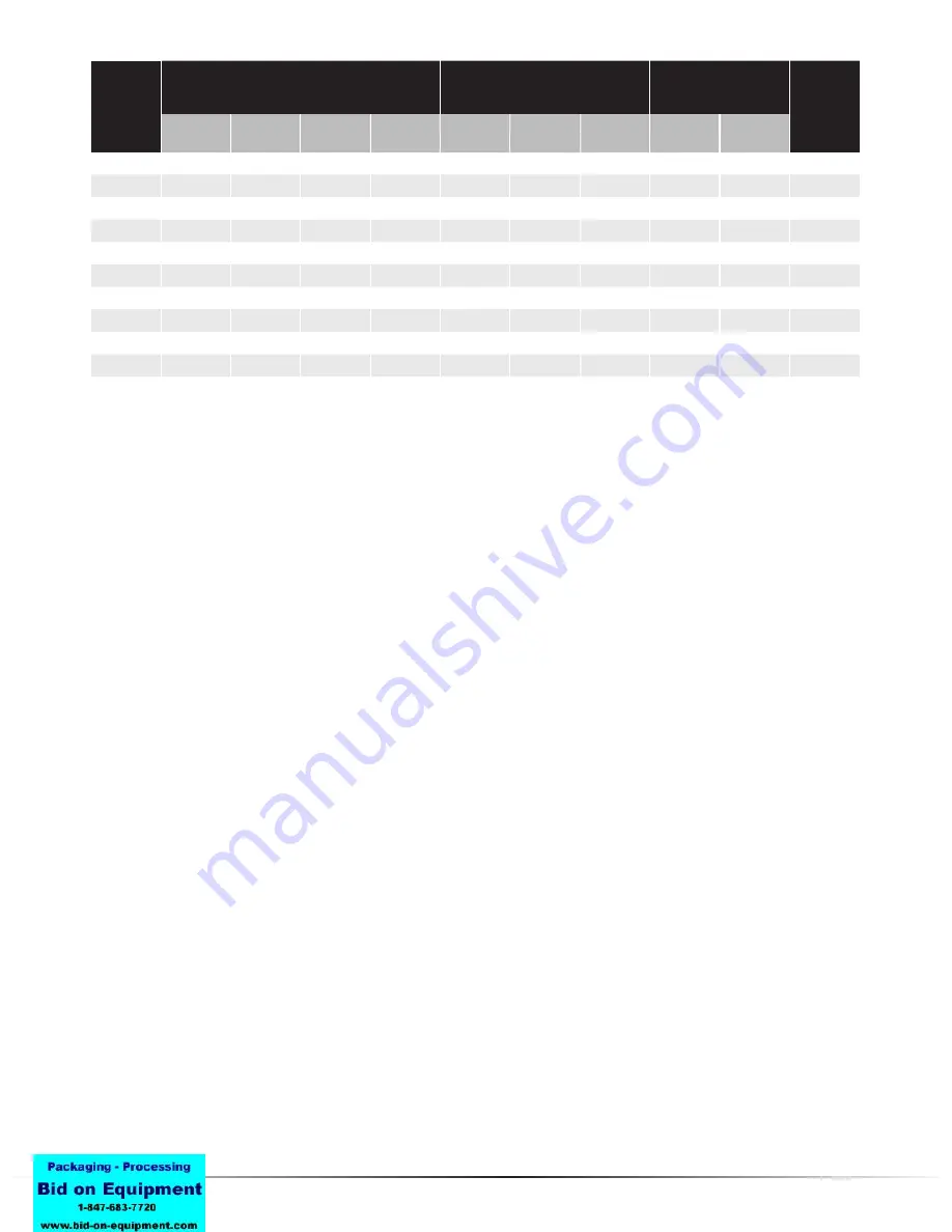
Blower
Size
Impeller Ends
Impeller Strips To Cylinder
Impeller Lobes
Max.
Temp Rise
-°F
Thrust
Ends
Gear End
Min.
Inlet
Center
Disch.
Fronts
Backs
1016
.010/.012
.023/.027
----
----
.014/.016
.010/.012
.014/.016
.020/.024
.010/.014
275°
1021
.010/.012
.032/.036
----
----
.016/.018
.010/.012
.016/.018
.022/.026
.010/.014
300°
1220
.010/.012
.034/0.38
----
----
.015/.017
.011/.013
.015/.017
.021/.025
.011/.015
275°
1222
.011/.015
.037/.041
----
----
.015/ .017 .011/ .013 .015/ .017 .021/ .025 .011/ .015
275°
1428
.013/.015
.032/.036
----
----
.019/.021
.012/.014
.019/.021
.022/.026
.012/.016
300°
1431
.014/.016
.035/039
----
----
.019/.021
.012/.014
.019/.021
.022/.026
.012/.016
300°
1639
.016/.018
.048/.052
----
----
.025/.027
.015/.017
.025/.027
.024/.028
.014/.018
300°
1643
.018/.020
.050/.054
----
----
.026/.028
.016/.018
.026/.028
.024/.028
.014/.018
300°
1833
.015/.017
.042/.046
----
----
.024/.026
.015/.017
.024/.026
.025/.029
.015/.019
300°
1838
.017/.019
.048/.052
----
----
.024/.026
.015/.017
.024/.026
.025/.029
.015/.019
300°
Table 2 - DVJ Clearances
Summary of Contents for Roots DVJ WHISPAIR
Page 22: ...DVJ WHISPAIR Dry Exhauster 23 Figure 15 Assembly of 10 thru 12 DVJ V V Belt Drive Splash Lube ...
Page 23: ...24 Dresser Roots Figure 16 Sectional Assembly of 10 thru 14 DVJ V Blowers ...
Page 24: ...DVJ WHISPAIR Dry Exhauster 25 Figure 17 Sectional Assembly of 16 20 DVJ Common Lube ...
Page 25: ...26 Dresser Roots Figure 18 Sectional Assembly of 1016 DVJ V Units ...


