background image

© DreamLine

 All Rights Reserved

© DreamLine

 All Rights Reserved

13

FLEX Shower Enclosure Panel manual Ver 3 Rev 4 072019

©2019 DreamLine. All Rights Reserved

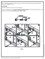
Fig 9

inside

inside

Ø 1/8”

Ø 1/8”

1

2

3

4

5

6

9.

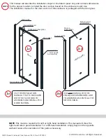
 From inside the shower, drill holes into the top and bottom Expanding rails through the predrilled 

holes using an 

Ø 1/8”

 drill bit.

ATTENTION:

Drill only through the first layer of the Expanding rail.

Secure the Expanding rails using 

ST4.0 x 10 Pan head screw


(#04) 

with the raised white washers. Cover 

exposed screw heads with 

Decorative covers (#06).  (Fig 9)

Summary of Contents for FLEX 42x72"

Page 1: ...t DreamLine com FLEX ENCLOSURE 34x46 34x58 SHOWER ENCLOSURE INSTALLATION INSTRUCTIONS 2019 DreamLine All Rights Reserved FLEX 34x46 34x58 Shower Enclosure Cover Page STEP 2 Install Return Panel FLEX E...

Page 2: ...information or additional details please refer to your model s web page on DreamLine com For more information about DreamLine Shower Doors Tub Doors please visit DreamLine com Right hand door installa...

Page 3: ...irements for this type of product and the care necessary for the safe installation and operation of the product FLEX 42x72 48x72 54x72 60x72 60x58 Shower and Tub Door manual Ver 1 Rev 4 072019 2019 Dr...

Page 4: ...are leveled and solid and will be able to support the total weight of the unit Also make sure the walls are at right angles Irregular installation surface level radius corners or improper angle of sid...

Page 5: ...out and identify all parts using the detailed diagram and packing list in this manual as a reference Before discarding the carton check for small hardware bags that may have fallen to the bottom of th...

Page 6: ...d DreamLine All Rights Reserved DreamLine All Rights Reserved Parts Diagram of Shower Door Components 4 FLEX 42x72 48x72 54x72 60x72 60x58 Shower and Tub Door manual Ver 1 Rev 4 072019 2019 DreamLine...

Page 7: ...or vanity During the initial assembly the entire frame can be flipped upside down top to bottom for either left or right hand door installation 1 Wall profile 2pcs 2 Panel Glass assembly 3 Wall ancho...

Page 8: ...served Model Overview 6 FLEX 42x72 48x72 54x72 60x72 60x58 Shower and Tub Door manual Ver 1 Rev 4 072019 2019 DreamLine All Rights Reserved Alluminum wall profile Stationary panel glass assembly Expan...

Page 9: ...Insert the end that is farther from the pivot hole Fig 1 top bottom outside inside outside inside pivot hole Right hand door installation shown door pivot hole insert this end 42 and 48 model door 23...

Page 10: ...0x72 60x58 Shower and Tub Door manual Ver 1 Rev 4 072019 2019 DreamLine All Rights Reserved Fig 2 TIP Apply some wax or dish soap to the screws to make assembly easier and to prevent stripping the scr...

Page 11: ...side Right hand door installation Left hand door installation inside panel panel door area door area panel door area inside 3 Slide both of the Wall Profiles 01 over the frame assembly Be sure that th...

Page 12: ...manual Ver 1 Rev 4 072019 2019 DreamLine All Rights Reserved Fig 5 Fig 6 Right hand door installation shown 1 2 5 Check the threshold of the finished opening to make sure that it is level This model...

Page 13: ...ssembly Fig 7 Fig 8 inside inside the door opening must be square 7 The opening for the door glass must be square Measure the top and bottom of the door opening and adjust the Expandable Rails as nece...

Page 14: ...5 16 8mm 3 4 5 16 8mm 3 1 2 9 Move the frame assembly aside and remove the Wall Profiles 01 Drill the holes into the walls using a 5 16 8mm drill bit and insert the Wall Anchors 03 Fig 9 10 Apply a b...

Page 15: ...8 Shower and Tub Door manual Ver 1 Rev 4 072019 2019 DreamLine All Rights Reserved Fig 11 Fig 12 1 2 3 11 Place the assembly back onto the threshold and into the panel side Wall Profile 01 first Fig 1...

Page 16: ...mLine All Rights Reserved Fig 13 Fig 14 outside pivot pivot bushing pre installed in the rails inside pivot rotation the door opening must be square Right hand door installation shown 13 Check and adj...

Page 17: ...5 1 2 3 4 Right hand door installation shown 15 Carefully install the Door Glass 17 onto the Top Bottom Pivot Hardware 16 Make certain that all gaskets are in place to protect the glass Cover the Pivo...

Page 18: ...s Reserved Fig 16 Fig 17 Right hand door installation shown outside door door 16 Trim the Bottom Sweep vinyl 08 to fit on both sides of the bottom pivot and attach both pieces to the bottom of the Doo...

Page 19: ...x72 48x72 54x72 60x72 60x58 Shower and Tub Door manual Ver 1 Rev 4 072019 2019 DreamLine All Rights Reserved Fig 18 inside panel outside Right hand door installation shown panel inside 18 Attach the V...

Page 20: ...rill bit 19b Secure the Expanding rails using the Round Head Screws ST4 2 10 04 and the raised white washers Cover the exposed screw heads and washers with the Decorative Caps 06 Fig 19 NOTE Do Not dr...

Page 21: ...oor manual Ver 1 Rev 4 072019 2019 DreamLine All Rights Reserved Fig 21 Right hand door installation shown The surfaces need to be clean and free of debris before applying silicone Allow 24 hours for...

Page 22: ...h the surface HARDWARE To ensure a long lasting finish wipe off the metal parts after each use with a soft cloth Do not use abrasive cleaners or cleaning products containing ammonia bleach or acid If...

Page 23: ...ights Reserved DreamLine All Rights Reserved DreamLine All Rights Reserved TEL 866 731 2244 FAX 866 857 3638 DREAMLINE COM For more information on DreamLine Shower Doors and Enclosures please visit Dr...

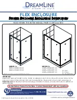
Page 24: ...efer to the model s web page on DreamLine com for the latest technical drawings installation manuals warranty information or additional product details FLEX ENCLOSURE SHOWER ENCLOSURE INSTALLATION INS...

Page 25: ...door section based on the enclosure model size The installation manual for the door section of this enclosure is packaged with the door glass FLEX Shower Enclosure Panel manual Ver 3 Rev 4 072019 2019...

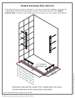
Page 26: ...Shower Enclosure Plan Vinyl Seals Installation Steps Product maintenance 6 5 4 2 3 17 15 7 8 16 This product should be installed by someone familiar with the construction requirements for this type of...

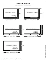
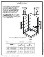
Page 27: ...7 16 max 30 1 2 1 1 2 minimum threshold required 28 7 16 min to 32 7 16 max SHDR 2230300 RT 01 04 SHDR 2234340 RT 01 04 RIGHT HAND RETURN PANEL SHOWN AS AN EXAMPLE 44 7 16 min to 48 7 6 max 34 1 2 1...

Page 28: ...34 1 2 44 7 16 min to 48 7 16 max 50 7 16 min to 54 7 16 max 32 7 16 min to 36 7 16 max 28 7 16 min to 32 7 16 max 56 7 16 min to 60 7 16 max 1 1 2 minimum threshold required 30 1 2 RIGHT HAND RETURN...

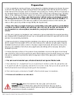
Page 29: ...plumber for all plumbing installation 4 Make sure that prior to beginning the installation the surfaces are leveled and solid and will be able to support the total weight of the unit Also make sure t...

Page 30: ...e Before discarding the carton check for small hardware bags that may have fallen to the bottom of the box If any parts are damaged or missing please contact DreamLine for replacement The shipping box...

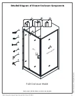
Page 31: ...erved Detailed Diagram of Shower Enclosure Components 6 FLEX Shower Enclosure Panel manual Ver 3 Rev 4 072019 2019 DreamLine All Rights Reserved 3 4 5 6 7 8 2 13 9 1 10 11 FLEX Enclosure Model RIGHT H...

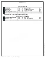
Page 32: ...2 Door assembly 1set 07 1pc 03 Wall anchor 8pcs 08 Bottom Sweep vinyl Vinyl Seal with Flexible Fin 1pc 04 ST4 0 x 10 Pan head screw 10pcs 13 Handle 1pc 05 ST4 2 x 40 Truss head screws 8pcs Return pane...

Page 33: ...OR AREA W PLACEMENT OF RETURN PANEL PLACEMENT OF DOOR SECTION RETURN PANEL W W1 W2 Return Profile Wall Profile RIGHT HAND RETURN PANEL SHOWN AS AN EXAMPLE door return panel 1 The overall width of the...

Page 34: ...rs 03 Apply silicone to the back surface of the Return Panel Wall Profile 11 and place it back in position on the wall Attach the Return Panel Wall Profile 11 to the wall with the ST4 2 x 40 Truss hea...

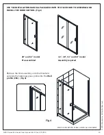
Page 35: ...eserved RIGHT HAND RETURN PANEL SHOWN AS AN EXAMPLE Fig 4 28 and 32 model Pre assembled Assembly required 42 48 54 and 60 model USE THE INSTALLATION MANUAL PACKAGED WITH THE FLEX DOOR TO ASSEMBLE AND...

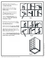
Page 36: ...Slide the Return Panel Assembly 09 into the Return Panel Wall Profile 11 Fig 6 5 Slide the Corner profile 10 over the vertical rail on the Return Panel Assembly 09 Drill 1 8 holes through the predril...

Page 37: ...and bottom expanding rails toward the Corner profile 10 Insert the Door Glass side into the Corner profile 10 Fig7 NOTE The maximum adjustment of the Expanding rails is 3 Do not expand the rails more...

Page 38: ...ide 1 8 1 8 1 2 3 4 5 6 9 From inside the shower drill holes into the top and bottom Expanding rails through the predrilled holes using an 1 8 drill bit ATTENTION Drill only through the first layer of...

Page 39: ...the magnetic strips are aligned and make full contact from top to bottom Drill holes into the aluminum profile of the Door assembly through the predrilled holes in the Wall profile 01 using an 1 8 dr...

Page 40: ...outside view 12 Attach the Vinyl Seal with Flexible Fin 07 to the vertical edge of the Stationary panel glass Measure and cut the Bottom Sweep vinyl 08 to cover the bottom edge of the door from the pi...

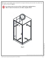
Page 41: ...s Reserved The surfaces need to be clean and free of debris before applying silicone Allow 24 hours for the silicone to cure before using the shower Fig 13 RIGHT HAND RETURN PANEL SHOWN AS AN EXAMPLE...

Page 42: ...ARE To ensure a long lasting finish wipe off the metal parts after each use with a soft cloth Do not use abrasive cleaners or cleaning products containing ammonia bleach or acid If accidentally used r...

Page 43: ...ights Reserved DreamLine All Rights Reserved TEL 866 731 2244 FAX 866 857 3638 DREAMLINE COM For more information on DreamLine Shower Doors and Enclosures please visit DreamLine com 2019 DreamLine All...

Reviews: