


-
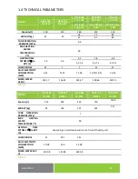
13
-
The heater is connected to the 230 V/50 Hz electric network using a fixed moving conductor with a switch
that turns off all network poles and the circuit breaker (protector).
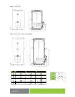
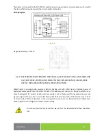
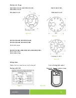
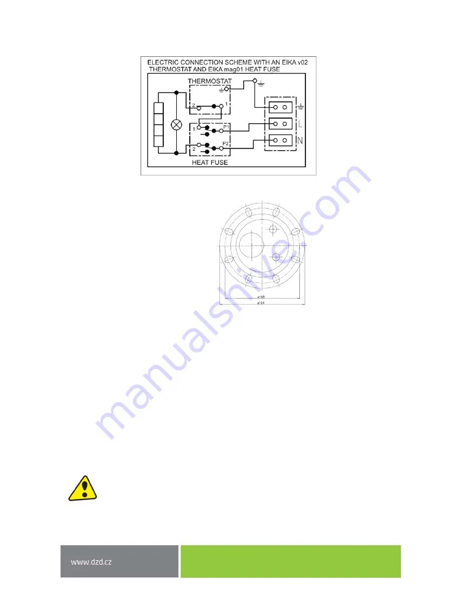
Wiring diagram:
Figure 8
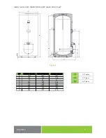
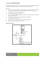
Flange lid fastening
-
8 x M10
Figure 9
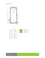
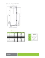
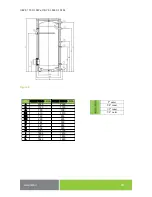
2.2.2
ELECTRIC INSTALLATION FOR
:
OKCE 160 S/2,2 KW, OKCE 160 S/3
-
6 KW, OKCE 200
S/2,2 KW, OKCE 200 S/3
-
6 KW, OKCE 250 S/2,2
KW, OKCE 250 S/3
-
6 KW, OKCE
300 S/1 MPA ,OKCE 400 S/1 MPA, OKCE 500 S/1 MPA
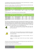
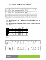
Water heater is equipped with universal electrical heating unit with either fixed or optional power of
heating elements (apart from OKCE 300 S/1 MPa).
The heating unit consists of a flange to which one or
three thermowells for ceramic heating units are welded, and a thermowell for regulation sensors (see
Figure 9, Figure 10, Figure 11). A unit is attached by either 8 M 10 screws with a 168 mm clearance or 12 M
12 screws with a 210 mm clearance.
In the wiring plastic cover, there is a thermostat and a safety fuse;
heater operation control light; and a lead
-
in wire bushing.
The sensors must be inserted all the way in; first the thermostat and then the safety
fuse.