background image


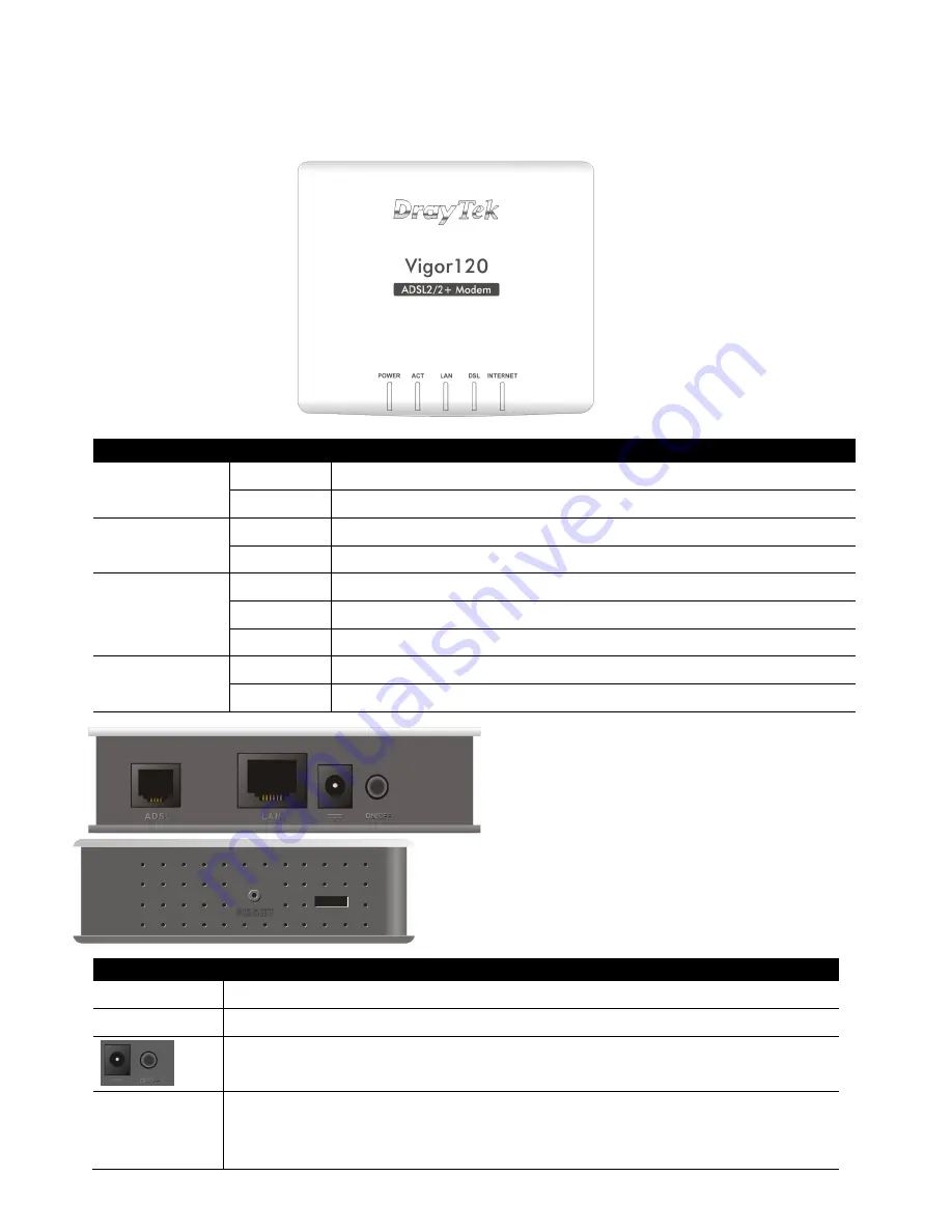
 Descriptions of Components


LED


Status 

Explanation


Power


On 

The modem is powered on.


Off 

The modem is powered off. 

ACT 

Off 

The system is not ready or is failed. 

Blinking  The system is ready and can work normally. 

LAN   

On


A normal connection is through its corresponding port. 

Off 

LAN is disconnected. 

Blinking


Data is transmitting (sending/receiving). 

DSL 

On 

DSL connection synchronized. 

Blinking  DSL connection is synchronizing. 


Interface


Description


ADSL   

Connecter for accessing the Internet through ADSL 2+. 

LAN


Connecter for local networked devices.


Connecter for a power adapter. 
ON/OFF: Power switch. 

RESET 

Restore the default settings. Usage: Turn on the router. Press the 
button and keep for more than 10 seconds. Then the router will 
restart with the factory default configuration. 

Summary of Contents for Vigor120 Series

Page 1: ......

Page 2: ...he following essential requirements and other relevant provisions of R TTE Directive 1999 5 EEC The product conforms to the requirements of Electro Magnetic Compatibility EMC Directive 2004 108 EC by complying with the requirements set forth in EN55022 Class B and EN55024 Class B The product conforms to the requirements of Low Voltage LVD Directive 2006 95 EC by complying with the requirements set...

Page 3: ...ge modem intended to pass your ADSL Internet connection directly through to a host device router PC games console etc without interruption or changing of the data e g NAT The Vigor 120 is simple to install being pre configured for most ISPs ŒPackage Contents Quick Start Guide RJ 45 Cable Ethernet RJ 11 to RJ 11 Cable ADSL Mains Power adapter ...

Page 4: ...sconnected Blinking Data is transmitting sending receiving DSL On DSL connection synchronized Blinking DSL connection is synchronizing Interface Description ADSL Connecter for accessing the Internet through ADSL 2 LAN Connecter for local networked devices Connecter for a power adapter ON OFF Power switch RESET Restore the default settings Usage Turn on the router Press the button and keep for more...

Page 5: ...he ADSL connection This section will guide you on how to install the modem for Physical connectivity 1 Connect the DSL interface to the MODEM port of external ADSL splitter with an ADSL line cable 2 Connect the LAN port to your host device PC router etc with the supplied RJ 45 ethernet cable 3 Connect the power adapter to the power port of the Vigor120 Connect the other end to the mains wall outle...

Page 6: ...PPoE PPPoA bridge modem it is not necessary to access the web interface of the Vigor 120 unless your ISP does not use the most common ADSL methods PPPoA and 0 38 as VPI VCI 1 Set up physical connectivity as explained in section 3 2 Configure the network device Firewall broadband router or a PC behind the Vigor 120 for PPPoE with the ISP Username and Password There are more guides to this with some...

Page 7: ...1 Click on Internet Access MPoA 2 Enable MPoA and configure this page as below ...

Page 8: ...c ch hn ni ic ca al l S Su up pp po or rt t If you are in the UK Ireland and need further assistance with configuration or troubleshooting of your Vigor 120 please visit www support draytek co uk For support outside of the UK Ireland please visit www drayek com or your local distributor instead Don t forget to check out the complete DrayTek range of routers firewall VoIP products and IP PBXs at ww...

Reviews: