background image

DA6 OPERATORS’ MANUAL

CONTROL DESCRIPTION

The DA6 has been designed for ease of use. It operates on balanced or unbalanced
signal levels in the range -15dB to +15dB.(ref. +4dBm)

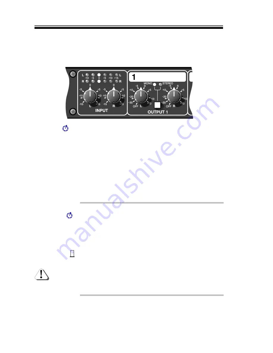
Input L&R

Used to set the optimal input gain for both Left and Right signals.
Use the display above to ensure the correct operating levels are
being attained. Adjustment in the range ±15dB is possible.
Separate controls are offered to permit the re-alignment of any
offset stereo image.

These controls also adjust the output level of the auxiliary ‘link’
jacks, which implies that any connected slave DA6 will only require
to have its input trims set to 0dB (vertically).

Input Display

Since the DA6 is normally used as a line amplifier, then it is quite
acceptable to ‘see’ signals in the positive gain region of this
display. However, ensure that the +15dB LED never illuminates
other than for brief instances, otherwise distortion will occur.

Output L&R

These controls should be used to set the optimal output level to
match the input section of the connected device, for both Left and
Right signals. Adjustment of ±15dB is possible. Normally, any
stereo image offset will have been corrected by the Left/Right input
controls. However separate output controls are also offered to give
total control of the stereo image.

Mono/Stereo

Selects whether the channel output is to be separate Stereo
signals or ‘summed’ to produce a Mono signal. If only one input is
used, this will be output to both sockets if Mono is selected. 

Caution should be used when operating the DA6 with two similar
stereo signals that are out-of-phase with each other. Under such
conditions, using the Mono mode will produce very little usable
output. LEDs show the status of the switch.

Summary of Contents for DA 6

Page 1: ...FETY CONSIDERATIONS page 1 INTRODUCTION page 2 INSTALLATION page 2 HEADPHONES pages 1 4 ISOLATING TRANSFORMERS page 3 CONTROL DESCRIPTIONS page 6 IF A FAULT DEVELOPS page 8 CONTACTING DRAWMER page 8 T...

Page 2: ...number copy of the original sales invoice and a detailed description of the problem Drawmer will not accept responsibility for loss or damage during transit This warranty is void if the product has be...

Page 3: ...WITH IEC 127 2 THE FUSE BODY SIZE IS 20mm x 5mm CAUTION MAINS CABLE DO NOT ATTEMPT TO CHANGE OR TAMPER WITH THE SUPPLIED MAINS CABLE CAUTION SERVICING DO NOT PERFORM ANY SERVICING REFER ALL SERVICING...

Page 4: ...utput LED bargraph and can be simultaneously heard at the front panel headphone jack An auxiliary pair of balanced output jacks provide a facility to connect further DA6 units where even more distribu...

Page 5: ...signal screen on one end of each of the cables connecting the DA6 to the patchbay If such measures are necessary balanced operation is recommended ISOLATION TRANSFORMERS The DA6 has the capability of...

Page 6: ...n integral fuse drawer containing the power fuse and a spare both of the same value to suit the mains voltage for which the unit has been supplied Removal of the drawer is only possible with the power...

Page 7: ...C 4a Exchange the 160mA fuse for a similar type rated at 315mA For conversion to 230Volt AC previously set to 115Volt AC 4b Exchange the 315mA fuse for a similar type rated at 160mA In both cases 5 Re...

Page 8: ...sitive gain region of this display However ensure that the 15dB LED never illuminates other than for brief instances otherwise distortion will occur Output L R These controls should be used to set the...

Page 9: ...er H Phone This control determines the amount of headphone amplifier drive Caution should be used when using high output levels and low impedance headphones Output Display This display shows the stere...

Page 10: ...ginal sales invoice and a detailed description of the problem Authorised returns should be prepaid and must be insured All Drawmer products are packaged in specially designed containers for protection...

Page 11: ...Watt into 8 Recommended Headphone Impedance 8 to 600 TRANSFORMER OPTION Outputs fitted with specified transformer will have the following specification Max Input Level 40 Hz 6dB for 0 5 THD Distortion...

Page 12: ...DA6 OPERATORS MANUAL BLOCK DIAGRAM...

Reviews: