– 5 –
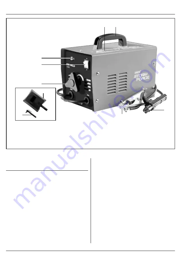
5. IDENTIFICATION – FIG.A
(1)
(2)
(3)
(5)
(8)
(9)
(7)
(6)
(4)
FIG.A
(1)
Carry handle
(2)
Welding current indicator
(3)
On/off switch
(4)
Thermal overload indicator
(5)
Current adjustment control
(6)
Electrode holder
(7)
Direct fit earth clamp
(8)
Face mask
(9)
Brush/hammer
6. ASSEMBLING THE
WELDER
Make sure the power supply information on the
machine’s rating plate is compatible with the power
supply you intend to connect it to.
A suitable plug must be fitted by a qualified
electrician.
This machines wiring has insulation stripped in
preparation for wiring a 16A plug (not supplied).
It is designed for connection to a 16amp
power supply
rated at 230V AC.
Because it is constructed mostly of metal parts, it is a
Class 1 machine; meaning, it must have an earth
connection in the power supply. This is to prevent
electrocution in the event of a failure.
NOTE: Remove the plug from the socket before carrying
out adjustment, servicing or maintenance.
Check that the electrical supply delivers the voltage and
frequency corresponding to the welding machine and
that it is fitted with a delayed fuse suited to the maximum
delivered rated current.
NOTE: The welding machines are set to the highest
voltage at the factory.
6.1 PREPARING THE WELDING
CIRCUIT
Connect the ground “lead” to the piece to be welded.
Connect the welding electrode to the electrode holder.
When the machine is turned on and the electrode
touches, the workpiece, the electrical circuit is complete,
this will result in the welding arc being produced.


