background image

- 3 -

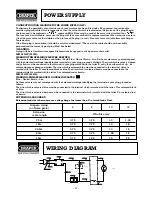
CONNECTING YOUR MACHINE TO THE POWER SUPPLY: (230V)

To eliminate the possibility of an electric shock your machine has been fitted with a BS approved, non rewireable
moulded plug and cable which incorporates a fuse, the value of which is indicated on the pin face of the plug. Should
the fuse need to be replaced an 

approved BS1362 fuse must be used of the same rating, marked thus

.

The fuse cover is detachable, never use the plug with the cover omitted. If a replacement fuse cover is required, ensure
it is of the same colour as that visible on the pin face of the plug (i.e. red). Fuse covers are available from your Draper
Tools stockist.
If the fitted plug is not suitable, it should be cut off and destroyed. *The end of the cable should now be suitably
prepared and the correct type of plug fitted. See below.

*WARNING:

A plug with bare flexible wires exposed is hazardous if engaged in a live power socket outlet.

MS250 230V (52352):
WARNING THIS APPLIANCE MUST BE EARTHED.

The mains lead is coloured Green and Yellow - Earth, Blue - Neutral, Brown - Live. As these colours may not correspond
with the coloured markings identifying the terminals in your plug, proceed as follows. The wire which is coloured green
and yellow must be connected to the terminal in your plug marked with the letter ‘E’ or by the earth symbol

or

coloured green or green and yellow. The wire which is coloured blue must be connected to the terminal which is
marked with the letter 'N' or coloured black or blue. The wire which is coloured brown must be connected to the
terminal which is marked with the letter 'L' or coloured red or brown.

MS250 110V (55810):
WARNING:THIS APPLIANCE IS DOUBLE INSULATED.

Blue – Neutral, Brown – Live.
As these colours may not correspond with the coloured markings identifying the terminals in your plug, proceed as
follows:
The wire which is coloured blue must be connected to the terminal which is marked with the letter ‘N’ or coloured black
or blue.
The wire which is coloured brown must be connected to the terminal which is marked with the letter ‘L’ or coloured red
or brown.

EXTENSION LEAD CHART:
Extension lead sizes shown assure a voltage drop of not more than 5% at rated load of tool.

POWER SUPPLY

WIRING DIAGRAM

Ampere rating

(on Name plate)

3

6

10

13

Extension

Wire Size mm

2

cable length

7.5m

0.75

0.75

1.0

1.25

15m

0.75

0.75

1.0

1.5

22.5m

0.75

0.75

1.0

1.5

30m

0.75

0.75

1.25

1.5

45m

0.75

1.25

1.5

2.5

Blue

Blue

Blue

X2
Capacitor

Red

Brown

Brown

Switch

Red

Brushes

Brown

Yellow-Green

Terminal Block

Blue

Red

1b

1a

1

Summary of Contents for MS250

Page 1: ...and safe use We recommend that this manual is read before any operation of the machine before performing any kind of adjustment to the machine and prior to any maintenance tasks By following all the general safety instructions contained in this manual it will ensure both machine and operator safety together with longer life of the tool itself All photographs and drawings in this manual are supplie...

Page 2: ...ursley Road Chandler s Ford Eastleigh Hampshire SO53 1YF England Declare under our sole responsibility that the product Stock Nos 52352 55810 Part Nos MS250 Description Compound Mitre Saws 230 Volt 110 Volt Testing Authority DET NORSKE VERITAS File number 41210533 230 Volt TUV Rheinland File number AM9956049 110 Volt To which this declaration relates is in conformity with the following directive s...

Page 3: ...e Should the machine develop any fault please return the complete tool to your nearest authorized warranty repair agent or contact Draper Tools Limited Chandler s Ford Eastleigh Hampshire SO53 1YF England Telephone 023 8026 6355 If upon inspection it is found that the fault occurring is due to defective materials or workmanship repairs will be carried out free of charge This guarantee does not app...

Page 4: ...as follows The wire which is coloured green and yellow must be connected to the terminal in your plug marked with the letter E or by the earth symbol or coloured green or green and yellow The wire which is coloured blue must be connected to the terminal which is marked with the letter N or coloured black or blue The wire which is coloured brown must be connected to the terminal which is marked wit...

Page 5: ... as cutters etc 16 AVOID ACCIDENTAL STARTING Make sure the switch is in the OFF position before plugging the machine into the power supply 17 NEVER LEAVE MACHINE RUNNING UNATTENDED Turn power off Do not leave machine until it comes to a complete stop 18 DO NOT ABUSE THE CORD Never carry the tool by the power cable or pull it from the socket Keep the power cable away from heat oil and sharp edges 1...

Page 6: ...missing or bent or has failed in any way or any electrical parts do not work properly turn the saw off and disconnect from the mains Replace damaged missing or failed parts before using the saw again 2 Plan your work to protect your eyes hands face and ears a Wear safety goggles not glasses that comply with BS2092 Using any power tool can result in foreign objects being thrown into the eyes which ...

Page 7: ...l jewellery and loose clothing c Tie back long hair d Roll long sleeves above the elbow 14 To avoid burns or other fire damage never use the saw near flammable liquids vapour or gases 15 To avoid injury from unsafe accessories use only accessories shown on the recommended accessories list in this manual 16 To avoid injury from accidental starting always unplug saw before disconnecting the guard in...

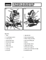
Page 8: ... Blade guard upper 6 Mitre scale 7 Bevel scale 8 Fence and scale 9 Dust bag 10 Dust port 11 Spindle lock 12 Bevel locking handle 13 Mitre locking assembly 14 Saw head locking pin 15 Blade 16 Blade flange wrench 17 Work piece clamp 18 Work piece supports 19 Work piece adjustable end stop 20 Adjustable stops Fig 1 Fig 2 ...

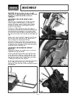
Page 9: ...ew in hole tighten screw and replace screw shim and washer Ensure this is located through the blade guard link Note With the blade guard link attached the guard should raise as the head is lowered towards the table and drop to cover the blade as the saw head is raised up Ensure this is fitted correctly ASSEMBLING THE WORKPIECE SUPPORT Fig 5 6 Carefully rest the saw on a stable surface so that the ...

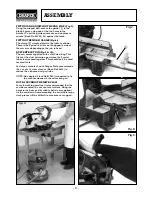
Page 10: ... This fits over the dust extraction port when the 2 metal tabs are squeezed together This should only be used for small cuts For large amounts of work Draper Tools recommends the use of a vacuum cleaner Stock No 64674 to reduce the airborne dust particles NOTE An adaptor Stock No 51280 is required to fix the vacuum cleaner to the extraction port NOTE SECURING THE MITRE SAW For safe working practic...

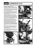
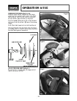
Page 11: ...lly touch the length of the square When set secure the mitre bolts on the underside Hold the saw head in the half way position with the blade guard raised up out of the way Stand the engineers square on the table and rest it against the blade Fig 13 Avoid the teeth for a true reading If the square lays flat against both surfaces no adjustment is required If adjustment is required loosen bolt Fig 1...

Page 12: ... Using the wrench remove the 2 bolts move the fence to the front or rear position and bolt in place Check squareness of fence to the blade again BEVEL CUTS ADJUSTMENT Fig 17 18 At the rear of the saw loosen locking handle to tilt the angle of the saw head Use the scale as a guide for the required angle When set in place resecure the locking handle OPERATION USE Fig 15 Fig 16 Fig 17 Fig 18 11 ...

Page 13: ...turning and with the wrench remove the locking flange NOTE The blade flange bolt has a left hand thread After the blade has been replaced ensure the flange and locking bolt are correctly and securely fitted and the lower blade guard reassembled OPERATION USE Fig 19 Fig 20 Fig 21 12 ON OFF TRIGGER SWITCH Fig 21 To operate the saw simply press the trigger switch in and the saw will start ARBOR WASHE...

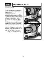
Page 14: ...p hands in position until trigger has been released and the blade has completely stopped Before making a cut make a dry run with the power off so you can see the path of the blade Fig 22 WARNING DO NOT TRY TO CUT SHORT PIECES YOU CANNOT PROPERLY SUPPORT THE WORKPIECE AND HOLD DOWN THE WORKPIECE BY HAND AND KEEP YOUR HAND THE REQUIRED DISTANCE FROM THE BLADE MITRE CUT When a mitre cut is required m...

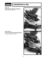
Page 15: ...desired bevel angle Stand to the left side of the handle to make the cut Fig 24 COMPOUND CUT When a compound cut is required select the correct bevel and mitre position Move with the handle to the mitre angle to make the cut Fig 25 OPERATION USE 14 Fig 24 Fig 25 ...

Page 16: ... workpiece on the blade The workpiece could suddenly jump or move and your hand could hit the blade Fig 26 27 AUXILIARY FENCE Certain types of moulding need a fence face extension not supplied due to the size and position of the workpiece Holes are provided in the fence to attach an auxiliary fence made of straight wood typically 1 2 thick by 3 high by 20 long The auxiliary fence is used with the ...

Page 17: ... x 4 workpiece in the vertical position on edge a spacer such as the auxiliary fence not supplied described on the previous page is required The fence is located in the front fence position Fig 30 When the filler blocks are attached to the fence with the face of the filler blocks pointing downwards the moulding must be placed on the table right side up This is the same position as it would be when...

Page 18: ...ng the workpiece so the workpiece does not sag and the hand holding the workpiece is positioned 4 or more from the blade path The support should let the workpiece lay flat on the base and worktable during the cutting operation Fig 31 Fig 31 WORKPIECE WORKPIECE SUPPORT OPERATION USE 17 ...

Page 19: ...de in a through cut or the slot produced by the blade in a non through or partial cut MITRE CUT An angle cutting operation made across the width of the workpiece RESIN A stick sap based substance that has dried and hardened REVOLUTIONS PER MINUTE RPM The number of turns completed by a spinning object in one minute SAWBLADE PATH The area of the workpiece or table top directly in line with either th...

Page 20: ...E SOLVENTS ON THE GUARD THEY COULD MAKE THE PLASTIC CLOUDY AND BRITTLE WARNING WHEN CLEANING LOWER GUARD UNPLUG THE SAW FROM THE OUTLET TO AVOID UNEXPECTED START UP OR ELECTRICAL SHOCK SAWDUST Periodically sawdust will accumulate under the worktable and base This could cause difficulty in the movement of the worktable when setting up a mitre cut Frequently vacuum up the sawdust RECOMMENDED ACCESSO...

Page 21: ...n authorised service agent for repair Cannot move mitre 1 Fence in rear position and 1 Loosen fence clamps retighten adjustment clamp tight before starting next cut 2 Sawdust under table 2 Vacuum out dust WEAR EYE PROTECTION Powerhead will not 1 Pivot misadjustment 1 Return to an authorised service rise fully agent for repair 2 Part failure 2 Authorized service agent 3 Pivot spring not replaced 3 ...

Page 22: ...NOTES 21 ...

Page 23: ...NOTES 22 ...

Page 24: ...6355 Fax 023 8026 0784 http www draper co uk e mail sales draper co uk Published by Draper Tools Ltd No part of this publication may be reproduced stored in a retrieval system or transmitted in any form or by any means electronic mechanical photocopying recording or otherwise without prior permission in writing from Draper Tools Ltd YOUR DRAPER STOCKIST ...

Reviews: