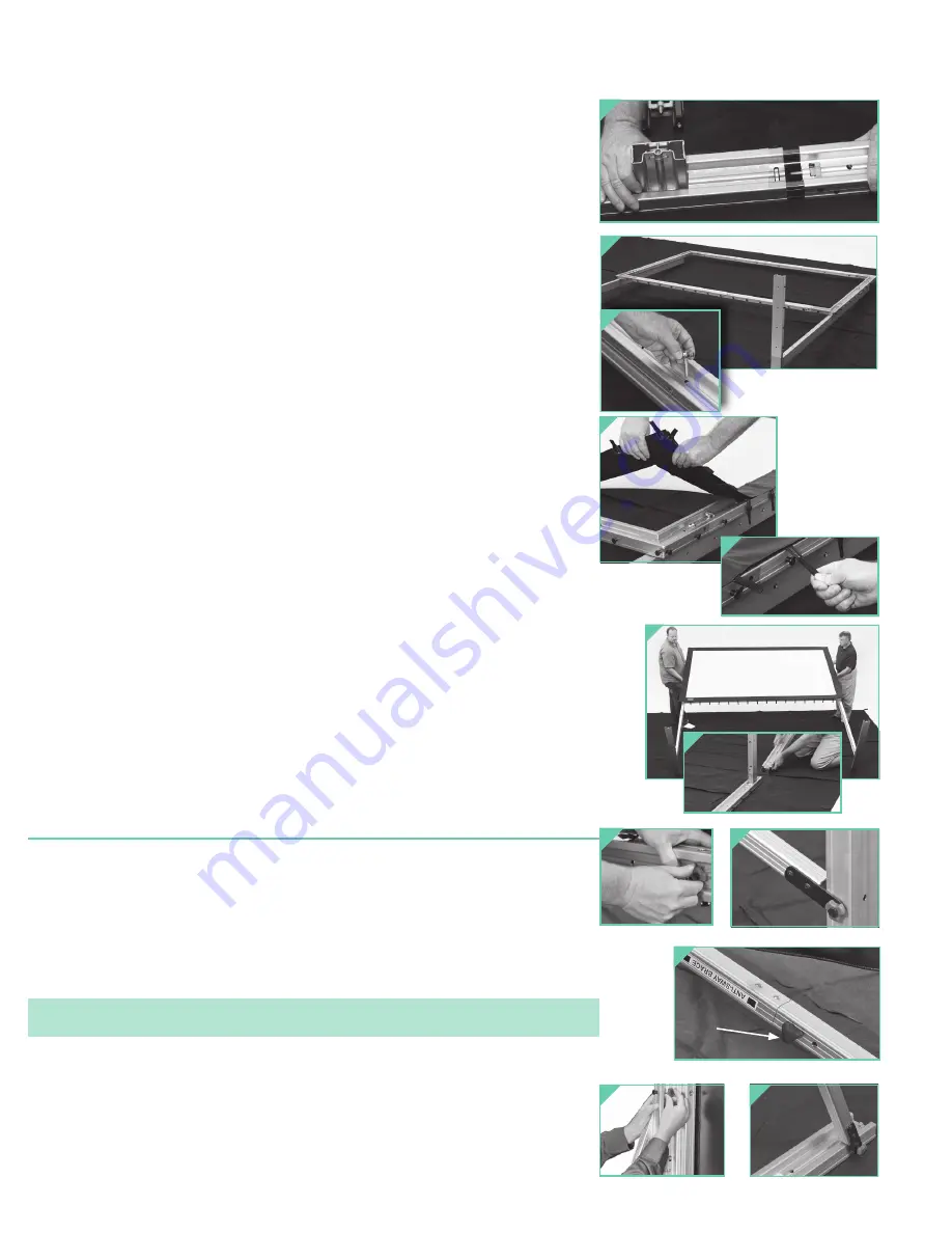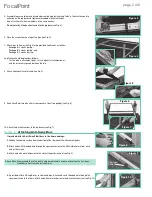
5. Assemble legs according to color-coded assembly map by inserting “forks” of front extension into
extrusion on the leg base and tighten color-coded attachment knobs.
Also, attach vertical frame members in the same manner.
Do not yet attach the back extension to the leg base
(see Fig. 3).
6. Place the screen frame on top of the legs (see Fig. 4).
7. Attach legs to frame (see Fig. 4) using provided Leg Cranks as follows:
Package A:
3 cranks per leg;
Package B
: 4 cranks per leg; and
Package C
: 5 cranks per leg.
Leg Cranks should be placed as follows:
1 at the lowest attachment point, 1 at the highest attachment point,
and the rest evenly spaced between the two.
8 Attach viewing surface to frame (see Fig. 5).
9 Raise FocalPoint into place (this step requires at least two people) (see Fig. 6).
10. Attach the back extensions to the leg bases (see Fig. 7).
Section 2 -
Attaching Anti-Sway Bars
If provided, attach Anti-Sway Stabilizers to the frame and legs.
1.
Unhook the viewing surface from the bottom of the frame near the attachment points.
2.
Attach ends with threaded hole through the square extrusion to the fifth visible hole in from each
end of the screen.
3.
Attach end with metal extension to the closest leg extrusion hole (see Fig. 8).
Please Note:
You may need to use the built-in adjustment knob to shorten or lengthen the Anti-Sway
Stabilizer so it will reach holes (see Fig. 9).
4.
If provided, attach HD Leg Braces to frame and legs. Attach ends with threaded hole through the
square extrusion to the frame. Attach end with metal extension to the back foot extrusion (see Fig. 10).
Figure 3
Figure 4
Figure 5
Figure 7
Figure 6
Figure 8
Adjustment
Knob
Figure 9
Figure 10
page 2 of 2
FocalPoint


