background image

Please note:

 If needed, the fabric panel heights can be adjusted so that the bottom 

edges of the fabric panels are aligned. On large units, this procedure should be 

done on only one panel at a time to minimize the amount of fabric weight that must 

be supported during the adjustment procedure. Install and adjust rear/upper panls 

before beginning on lower/front panels.

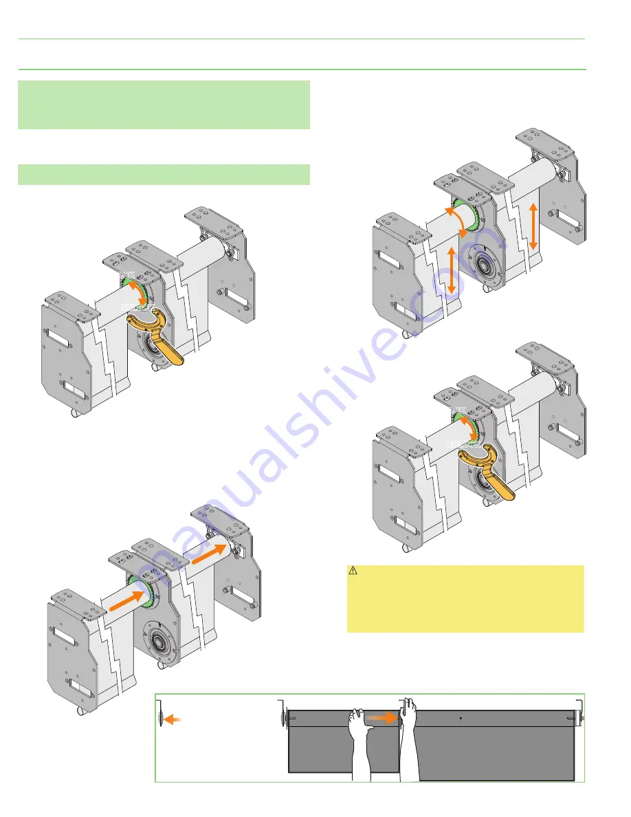
1. 

Unlock height adjuster mechanism 

(or coupler shaft receiver)

 located at the operator-

end of fabric roller assembly being adjusted by rotating the metal ring about ¼ 

turn counterclockwise when viewing the face of the coupler  assembly 

(Fig. 10)

.

Please note:

 Do not use this procedure to adjust the operator-end assembly. Use the 

limits to set the down travel of the operator-end assembly.

5. 

Tighten the locking ring by firmly rotating it approximately ¼ turn 

clockwise 

(reverse of step 1)


(Fig. 13)

.

6. 

Operate the unit to check for proper fabric position, tracking, etc.

2. 

Push the fabric/roller assembly being adjusted toward the operator-end of the 

unit. The fabric/roller assembly will move approximately

 3/16

(8 mm)

 toward the 

operator end 

(Figs. 11 and 12)

.

3. 

Rotate the fabric/roller assembly being adjusted in either direction to raise or 

lower the fabric panel 

(Figs. 12 and 13)

.

4. 

Allow the fabric/roller assembly being adjusted to move back, away from the 

operator end of the unit, and check the position of the fabric panels.

 Caution:

 Ensure the locking ring on the idler-end coupler 

assembly is fully tightened following height adjustment. Ensure 

you are wearing a heavy glove on the hand you will be using to 

grip the locking ring. Tighten the locking ring until it is fully 

locked and you cannot rotate it any further. Check to ensure is it 

tight and will not work loose. If you cannot tighten by hand, you 

may need to use a flat screwdriver or other tool to assist.

Section 6 -

 Fabric/Roller Assembly Alignment 

(Steps are shown for right-hand operators)

Unlock coupler shaft receiver

by rotating the metal ring about

 turn counterclockwise.

LOCK

UNLOCK

Figure 10 

Rotate the fabric/roller assembly 

being adjusted to adjust 

the fabric length.

Figure 12

Tighten the locking ring

by firmly rotating it

approximately 1/4 turn

clockwise.

 (Inverse of Step 1)

LOCK

UNLOCK

Figure 13

Push the fabric/roller assembly 

approximately 

 toward 

the operator end of the unit.

Figure 11 

Figure 14

Operator Panel

Location of next panel

page 8 of 12

Dual Roller Coupled Motorized FlexShades

®


(Large Hardware)

Summary of Contents for FlexShade D MO Series

Page 1: ...ction 8 Electrical Connections 9 11 Section 9 Dimensions 12 Section 10 Large Hardware Dimensions 12 FLEXSHADE D MO Locking Ring SHADE FABRIC SHADE FABRIC Motor Plate Idler End Bracket Spanner Wrench Motor End Bracket Coupler Bracket Assembly TOOLS REQUIRED POWER DRILL PENCIL TAPE MEASURE HARDWARE by others LEVEL Draper Inc 411 S Pearl St Spiceland IN 47385 draperinc com 765 987 7999 800 238 7999 2...

Page 2: ...nd regulations should be reviewed before installation and use 17 Failure to precisely follow installation guidelines invalidates all warranties 18 Custom products installations may not be reflected in this manual Call Draper Inc if you have questions about the installation of custom products or any questions about your installation Before Beginning Installation 1 Look for any job site conditions t...

Page 3: ...he same steps used for the idler end Please Note If the assembly will not fully seat in the roller retract the shaft if applicable and tap the assembly with a rubber mallet Be careful not to damage the coupler Ensure the locking ring on the idler end coupler assembly is fully tightened before installing roller into brackets There should be no play in the locking ring If the locking ring is loose t...

Page 4: ... VENT HOLES POCKET MOUNTING HOLES ENDCAP MOUNTING HOLES Headbox Headbox Closure Panel Closure Panel WALL Brackets mounted to continuous blocking by others secured to building structure Ceiling by others 1 2 Section 3 Pocket Headbox Installation PLEASE NOTE Installer must provide adequate clearance for removal of Roller Assembly during installation and maintenance PLEASE NOTE Headbox must be mounte...

Page 5: ...Wall Clip pre attached to headbox Window WALL 8 216mm 6 165mm 7 186mm 2 59mm 3 86mm 22mm 1 6mm 19mm 2 60mm 1 38mm 3 76mm Closure Panel Figure 3 E Section 4 Installing Closure Panel Follow Steps 1 2 Fig 4 Headbox Headbox Closure Panel Closure Panel Figure 4 1 2 page 5 of 12 Dual Roller Coupled Motorized FlexShades Large Hardware ...

Page 6: ...ed with the marked location Please Note There is no retractable shaft in the idler end assembly on the idler end shade furthest from the operator This idler assembly utilizes a sliding pin and retainer clip Please Note These instruction steps are for installing brackets brackets one at a time Brackets brackets may also all be installed at the same time prior to installing roller fabric assemblies ...

Page 7: ...ed roller by rotating the metal ring clockwise about 180 when viewing the face of the coupler assembly see Operating the Retractable Shaft and Fig 5 until the shaft extends fully into the receiver of the fabric roller assembly being installed 6 Installer 2 extends the coupler shaft of the fabric roller assembly being installed to the intermediate position by rotating the ring clockwise about 120 s...

Page 8: ...ate the fabric roller assembly being adjusted in either direction to raise or lower the fabric panel Figs 12 and 13 4 Allow the fabric roller assembly being adjusted to move back away from the operator end of the unit and check the position of the fabric panels Caution Ensure the locking ring on the idler end coupler assembly is fully tightened following height adjustment Ensure you are wearing a ...

Page 9: ...k Bottom View Side View GLASS SIDE ROOM SIDE Front Back Bottom View Side View Screws Front Back Bottom View Side View GLASS SIDE ROOM SIDE Screws Front Back Bottom View Side View GLASS SIDE ROOM SIDE PUSH BUTTON LIMITS Standard right hand motor configuration shown SCREW TYPE LIMITS Standard right hand motor configuration shown Section 8 Electrical Connections Shade operates on 110 120V 60 Hz curre...

Page 10: ...TE 2 WHITE 1 BLACK 3 RED 4 GREEN 2 WHITE W B R G To Switch 120VAC To Motor 60 1 5 m Standard 12 30 5 cm Standard M12 Connector for 4 Wire Motors Ø 0 61 15 5 mm Dashed Wiring by Electrician Controls System Overview Sonesse RTS 120VAC Motors M12 Connector B W G RTS MOTOR 120V 110 120V Line DecoFlex Wire Free Keypad Telis 1 RF Remote STOP Data Cable Pin Out RJ45 Connector TE 1 DATA ORANGE WHITE 2 DAT...

Page 11: ...ector Network Device Connector Handheld Remote Wireless Gateway Wall Switch AV Gateway Network Device Connector Contact Closure Interface Controls System Overview 120VAC Motors M12 Connectors B W G 110 120V Line B W G 110 120V Line RS485 120VAC Motor RS485 120VAC Motor Overview C Motors Data Cable Pin Out RJ45 Connector 1 ORANGE WHITE 2 ORANGE 3 GREEN WHITE 4 BLUE 5 BLUE WHITE 6 GREEN 7 BROWN WHIT...

Page 12: ...m This number may be greater depending on motor selection Contact Draper for motorverification BRACKETS Section 10 Large Hardware Dimensions CLOTH WIDTH Pocket Headbox SHADE WIDTH Large Dual Roller Pocket Headbox Dimensions 8 216mm 8 216mm 6 165mm 7 186mm 2 59mm 3 86mm 3 76mm 22mm 1 6mm 19mm 2 60mm 1 38mm 2 4mm Shade Width and Rough Opening will vary depending on motor selection 7 181mm 4 114mm pa...

Reviews: