background image

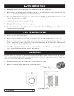
SAFETY INSTRUCTIONS

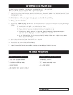
SET – UP INSTRUCTIONS

AIR FITTING

1.   Always wear safety goggles and protective gloves while operating foam unit.

2.   Avoid  contact  of  cleaning  agents  with  skin  and  eyes.    If  contact  occurs  rinse  affected  area  with

water for 15 minutes and get medical attention if needed.

3.   After use, relieve all remaining pressure in the system by unplugging the air line from the unit and

opening the discharge ball valve.

4.   Incoming air pressure cannot exceed 100 psi.

5.   Never point the discharge ball valve at anyone.

6.   Be sure to flush the unit with fresh water for 5 minutes when switching from an alkaline to an

acid or an acid to an alkaline.

1.   Remove all parts from shipping box.

2.   Clip the cable tie holding the air fitting, cotter pins, and axle washers from the leg of the cart.

3.   Place one of the washers on one of the axles, then slip a wheel on the axle followed by a  second

washer, then insert a cotter pin into the hole in the axle and bend the cotter pin to keep it from

falling out.  Repeat this for the other side.

4.   Screw the air plug into the brass fitting on the side of the control box.  Be sure to hold the brass

fitting while turning the air plug.  Do not over–tighten.

Because there are a number of different air fitting standards available, Dramm foamers do not come

with a pre-installed air fitting. The air inlet offers both 1/4” female pipe thread and 3/4” male pipe

thread as connection options for your fitting. 

1. Choose an air fitting that matches those on your compressor outlet. 

2. Apply teflon tape or pipe sealant to the thread and install.

Foamer Manual

4

Summary of Contents for FM20

Page 1: ...FOAMER FM20 FM50 Foamer Owners Manual FM50 FM20...

Page 2: ...x Assembly Diagram 7 Box Parts List 8 Hose Assembly Diagram Parts List 9 FM20 Plumbing Assembly Diagram Parts List 10 FM50 Plumbing Assembly Diagram Parts List 11 FM20 Frame Assembly Diagram 12 FM20 F...

Page 3: ...ncluding any warranties of merchantability or fitness for a particular purpose are expressly excluded In no event shall Dramm Corporation be liable for loss of product profit or any other special inci...

Page 4: ...lip the cable tie holding the air fitting cotter pins and axle washers from the leg of the cart 3 Place one of the washers on one of the axles then slip a wheel on the axle followed by a second washer...

Page 5: ...in 1 4 turn increments allowing 30 seconds between adjustments until proper consistency of foam is achieved D If the valve is open too far it can cause the pump to stall out If this occurs begin begi...

Page 6: ...charge hose is not kinked in any way that would reduce or obstruct solution flow 5 Check for plugged strainer Replace strainer if necessary STRAINER MUST BE USED 6 If wet foam dry foam valve is open t...

Page 7: ...FM BOX ASSEMBLY DIAGRAM Foamer Manual 7...

Page 8: ...229 BARB 3 8 X 1 4 MPT NY 1 17 250061 1 4 HOSE 12 18 220410 1 2 O D SPRING CLAMP 2 19 200031 PUMP AIR DRIVEN 5 0 GPM VITON 1 20 250040 1 2 HOSE 18 21 250062 3 8 HOSE 14 22 250062 3 8 HOSE 14 23 100100...

Page 9: ...AMM HOSE PROTECTOR 1 4 220051 NIPPLE HEX 1 2 NPT STL 2 5 17033 25F DRAMM HOSE 1 2 X 25FT 1PC YL W F 1 5 17033 50F DRAMM HOSE 1 2 X 50FT 1PC YL W F 1 5 17033 75F DRAMM HOSE 1 2 X 75FT 1PC YL W F 1 6 23...

Page 10: ...MM DESCRIPTION QTY 1 220500 FITTING BLKHD 1 2FPT 1 2 220127 ELBOW ST 1 2 PT NY 1 3 220005 1 2 MPT CLOSE NIPPLE CPVC 2 4 220602 1 2 FPT TEE PVC 1 5 230029 1 2 FPT PVC BALL VALVE 1 6 220211 1 2 NPT X 1...

Page 11: ...DESCRIPTION QTY 1 220505 FITTING BULKHEAD 3 4 FPT HD 1 2 220127 ELBOW ST 1 2 PT NY 1 3 220005 1 2 MPT CLOSE NIPPLE CPVC 2 4 220602 1 2 FPT TEE PVC 1 5 230029 1 2 FPT PVC BALL VALVE 1 6 220211 1 2 NPT...

Page 12: ...Foamer Manual 12 FM20 FRAME ASSEMBLY DIAGRAM...

Page 13: ...0300 1 4 FLAT WASHER 16 4 110002 1 4 20 X 3 4 HHCS 4 5 610020 20 GALLON TANK 1 6 110276 5 16 18 NYLON LOCK NUT 8 7 110301 5 16 WASHER 16 8 D11093A V 20 GALLON CART BASE ASSEMBLY 1 9 500051 6 CASTER 2...

Page 14: ...Foamer Manual 14 FM50 FRAME ASSEMBLY DIAGRAM...

Page 15: ...EMBLY 1 4 500001 WHEEL 3 X 12 2 5 110007 1 4 20 X 1 75 HHCS 4 6 110300 1 4 FLAT WASHER 16 7 D11820A AXLE 1 8 118100 1 8 HAIR PIN 2 9 110275 1 4 20 NYLON LOCK NUT 8 10 500050 SWIVEL CASTER 2 X 8 2 11 1...

Page 16: ...DRAMM FOAMER MANUAL NOTES 2000 North 18th Street P O Box 1960 Manitowoc WI 54221 1960 USA dramm com 920 684 0227 1 800 258 0848 FAX 920 684 4499 information dramm com 12 2020...

Reviews: