A
PWR
P.LK
V
VMM860AS
A / V
R F
C A T V
B C T V
CATV
+100
5
2
Specifications subject to change without notice or obligation.
54 to 864 MHz; Standard, HRC, or IRC CATV channels 2 to
135, Broadcast TV channels 2 to 69.
Automatic (+12.5 kHz, +25 kHz, or none as required).
+45 dBmV minimum (10 dB adjustment range).
75 Ohms, 8 dB return loss.
Audio carrier level, adjustable from -22 to -12 dB
referenced to video carrier level.
Within ±5 kHz
From 54 to 864 MHz, less than 3 dB change.
±1 dB
4.5 MHz
-60 dBc, (-15 dB A/V ratio and output level of +45 dBmV).
65 dB typical, 4 MHz bandwidth.
-78 dBc typicial, 4 MHz bandwidth @ +45 dBmV output.
0.65 Vp-p to 1.5 Vp-p. Gain adjust with front panel control.
Trips at 87.5 % depth of modulation. (VMM860AS only)
75 Ohms, return loss of 26 dB minimum.
20 Hz to 4.2 MHz, ±1 dB.
Within 50 nSec. of FCC predistortion.
3% maximum (10 to 90% APL).
3
0
maximum (10 to 90% APL).
125 mV rms to 2.5 V rms. Manual gain adjust with
front panel control.
Greater than 10 K Ohms, unbalanced.
75
µ
Sec. normal, defeatable (flat) by rear panel switch for
BTSC baseband stereo compatibility.
40 Hz to 15 kHz, ±1.0 dB referenced to 75
µ
Sec.
pre-emphasis curve.
40 Hz to 100 kHz, ±0.5 dB if pre-emphasis is defeated.
65 dB.
Less than 0.5 %.
250 mV to 2.5 V rms for 25 kHz L+R deviation.
Trips at ±25 kHz L+R deviation.
Greater than 10 K Ohms, unbalanced.
> 30 dB from 100 Hz to 10 kHz.
> 25 dB from 10 kHz to 14 kHz.
±1 dB of 75
µ
Sec pre-emphasis curve, 50 Hz to 14 kHz.
> 60 dB
Less than 0.5 %
+12 V ±5% at 200 mA (AG) or 220 mA (AS).
+5 V ±5% at 350 mA (AG) or 400 mA (AS).
0
0
C to +50
0
C ambient.
1” W x 3.5” H x 7.5” D (AG) or 8" D (AS)
12 oz. (AG) or 13.5 oz. (AS)
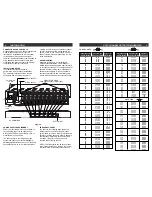
RF
Frequency Range:
FCC Frequency Offsets:
Output level:
Output Impedance:
A/V Ratio:
Frequency Stability:
Output Flatness:
Output Amplitude Stability:
Intercarrier Frequency:
Spurious Outputs (5 to 900 MHz):
In-Channel C/N:
Broadband Noise:
VIDEO
Input Level for 87.5% Modulation:
Video Over-modulation LED:
Input Impedance:
Frequency Response:
C/L Delay:
Differential Gain:
Differential Phase:
AUDIO, VMM860AG
Input Level for +/- 25 kHz Deviation:
Input Impedance:
Pre-emphasis:
Frequency Response:
S/N ratio:
Total Harmonic Distortion:
AUDIO, VMM860AS
Input Level:
Over Modulation Indicator:
Input Impedance:
Channel Separation:
Frequency Response:
S/N Ratio:
THD:
GENERAL
DC Power Input:
Operating Temperature:
Size:
Weight:
VMM860AG
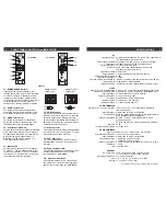
POWER/
ERROR
AUDIO
VIDEO
A / V
B C
T V
C A T V
CATV
+100
R F
2
5
F1
F2
F3
F4
F5
F6
F7
Figure 1
F1 - POWER/ERROR Indicator
Lights when the unit is connected to the
required source of DC power via the rear panel
DC INPUT connector. A flashing condition
indicates an invalid channel setting or other
conditions that would cause the unit to operate
on an invalid channel. The RF output is
switched off for flashing (ERROR) conditions.
F2 - AUDIO Level Control
The setting of this screwdriver adjustment
determines the aural carrier deviation. Clock-
wise rotation increases the carrier deviation.
F3 - VIDEO Level Control
The setting of this screwdriver adjustment
determines the video modulation level. CW
rotation increases the modulation depth.
F4 - Channel Number Switch
Sets the desired operating channel for standard
CATV channels 02 through 135 or Broadcast
TV channels 02 through 69. See also Item F5
which sets the type of channel (CATV or
Broadcast TV) and sets the leading “1” for
CATV channels 100 through 135.
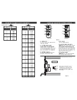
F5 - Mode Switch
Sets the type of channel, CATV or Broadcast
TV (“BC TV”). The first position of the switch
(“+100”) sets a leading “1” for CATV channels
100 through 135. See also Item F4 for setting
the channel. Here are two examples:
Setting for CATV
Setting for CATV
channel "125"-
channel "25"-
CATV
+100
CATV
BC
TV
2
5
CATV
+100
CATV
BC
TV
2
5
F6 - A/V Ratio Control
This screwdriver adjustment varies the level of
the aural carrier over a range from 12 to 22 dB
below the visual carrier. Typically, the aural
carrier should be adjusted to approximately 15
dB below the visual carrier. Clockwise rotation
increases the aural carrier level.
F7 - RF Output Level
This screwdriver adjustment permits adjustment
of the RF output level over a minimum of 10 dB
range. Maximum output is at full CW.
F8 - P. LK (Pilot Lock)
This LED indicates that the BTSC circuitry in
the VMM860AS has locked to the video sync
reference.
F9 - Audio Overmodulation
This LED illuminates when the audio input level
reaches full modulation. Set F2 for just an
occasional flicker. (VMM860AS)
F10 - Video Overmodulation
This LED illuminates at 87.5% video modula-
tion. Advance F3 CW until F10 just lights then
back off until F10 just goes out. (VMM860AS)
F8
F9
F10
VMM860AG
VMM860AS
2
FRONT PANEL CONTROLS and INDICATORS
SPECIFICATIONS 7


